
System, method and apparatus for supporting and concealing radio antennas

a radio antenna and antenna support technology, applied in the direction of antennas, antenna details, elongated active element feeds, etc., can solve the problems of not being well received by local communities, needing more antennas, and customers' placement of antennas

Active Publication Date: 2011-10-11
SOLAR COMM INT
View PDF40 Cites 2 Cited by
  • Summary
  • Abstract
  • Description
  • Claims
  • Application Information

AI Technical Summary

Benefits of technology

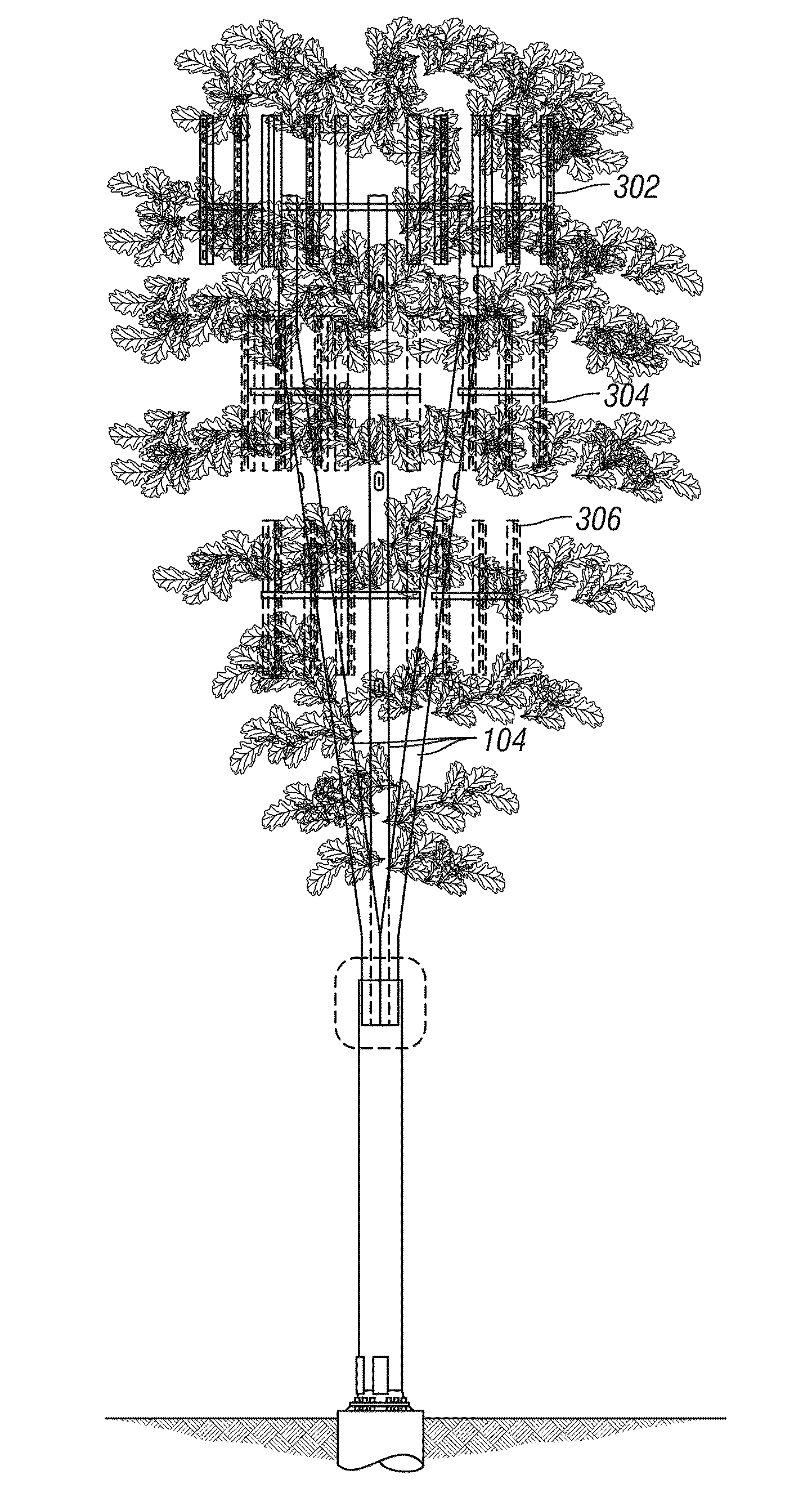
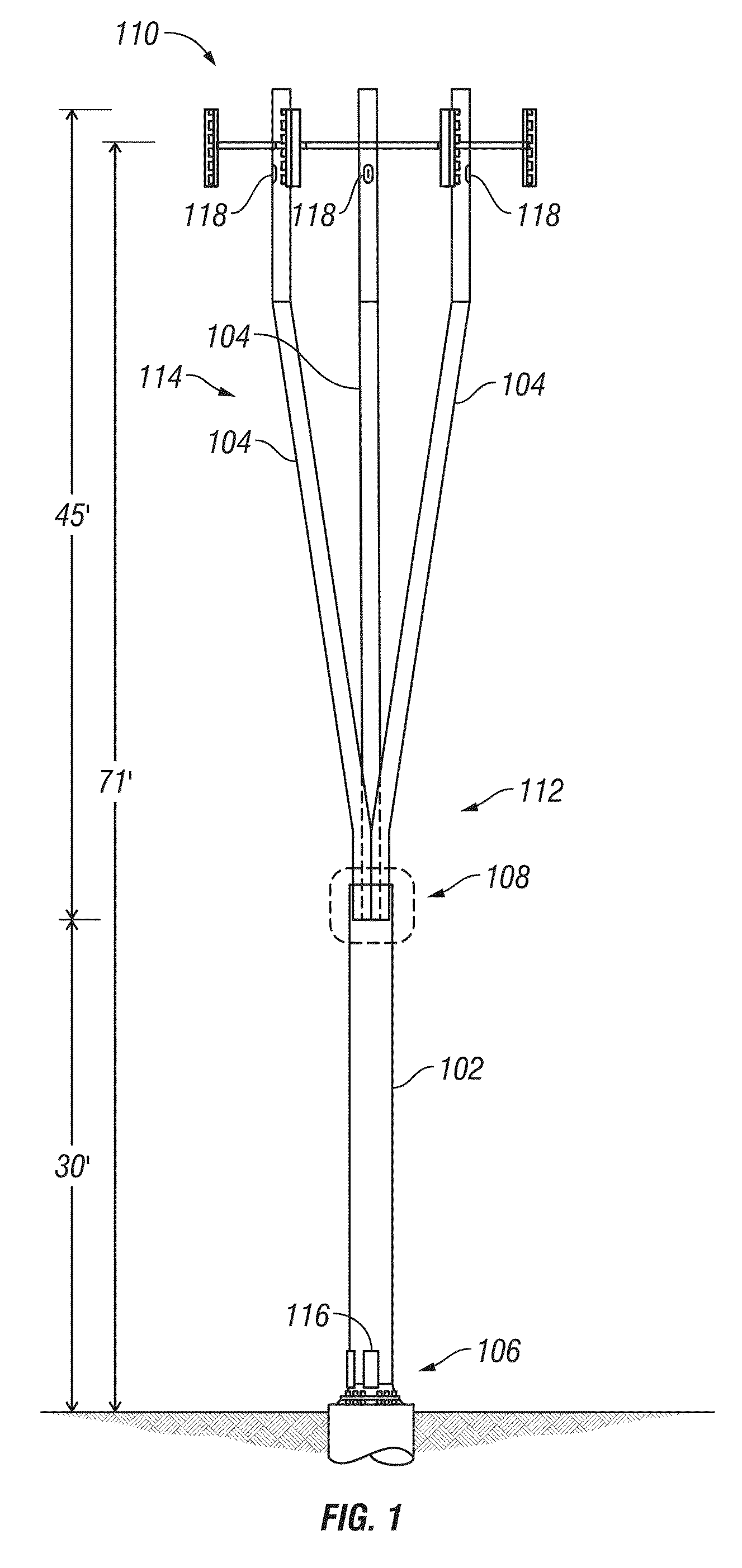
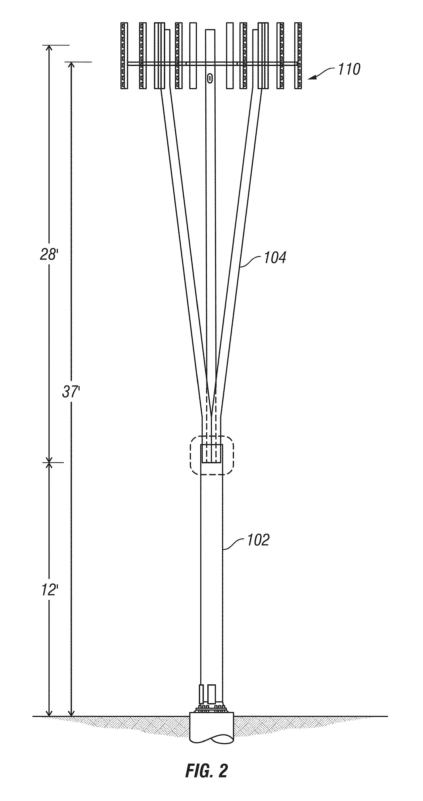
"The present invention is a multi-trunk antenna structure that includes a main trunk and a plurality of upper trunks. The upper trunks extend upwardly, at a desired angle, from the main trunk, thereby providing a desired girth of the structure near the top. The structure also includes a plurality of antennas attached to desired upper trunks at a desired height above ground level, and the antennas can be adjusted to desire azimuths. The structure can also include a plurality of branches protruding of the upper trunks. The invention provides a more efficient and effective antenna structure for transmitting and receiving signals."

Problems solved by technology

While consumer demand for increased coverage and capability of wireless communications system continues to increase, and thereby increase the need for more antennas, there is resistance by the same customers for the placement of the antennas.
Typically, radio antennas are not aesthetically pleasing and are generally not well received by the local communities.

Method used


Image

  • System, method and apparatus for supporting and concealing radio antennas
  • System, method and apparatus for supporting and concealing radio antennas
  • System, method and apparatus for supporting and concealing radio antennas

Examples


Embodiment Construction

[0030]Certain embodiments as disclosed herein provide for methods and systems for communication over a broadband wireless air interface. After reading this description it will become apparent how to implement the invention in various alternative embodiments and alternative applications. However, although various embodiments of the present invention will be described herein, it is understood that these embodiments are presented by way of example only, and not limitation. As such, this detailed description of various alternative embodiments should not be construed to limit the scope or breadth of the present invention as set forth in the appended claims.

[0031]There have been some attempts to conceal antennas. For example, if antennas are place on a building, such as a rooftop, there have been boxes, cupolas, and other structures to cover the antennas. While this technique may have some success in industrial, or commercial, areas they are generally not as acceptable in residential and ...


PUM


Abstract

A multi-trunk antenna structure that includes a main trunk and a plurality of upper trunks is provided. The upper trunks extend upwardly at a desired angle from the main trunk and provide a desired girth of the structure near the top. A plurality of antennas are attached to desired upper trunks at a desired height above ground level. The antennas can be adjusted to a desire azimuth. The antenna structure can include branches so that it resembles a Eucalyptus tree, an Oak tree, or other type of tree. The trunks of the structure can provide raceways for antenna cabling.

Description

RELATED APPLICATION[0001]The present application is a continuation of U.S. patent application Ser. No. 11 / 778,476 filed 16 Jul. 2007, which claims the benefit of U.S. provisional patent application Ser. No. 60 / 807,598 filed 17 Jul. 2006, each of which is incorporated herein by reference in its entirety.BACKGROUND[0002]1. Field[0003]The present invention relates to antenna support structures, and more particularly to a system, method, and apparatus that supports and conceals radio antennas.[0004]2. Related Art[0005]The widespread growth of wireless communications has resulted in a dramatic increase the number of radio antennas placed throughout communities. While consumer demand for increased coverage and capability of wireless communications system continues to increase, and thereby increase the need for more antennas, there is resistance by the same customers for the placement of the antennas. Typically, radio antennas are not aesthetically pleasing and are generally not well recei...

Claims


Application Information

Patent Timeline
Patent Type & Authority Patents(United States)
IPC IPC(8): H01Q1/12
CPCH01Q1/1242
Inventor RENFRO, ROBERTSMITH, RODGER
Owner SOLAR COMM INT
Learn More