
Transporter vehicle

a technology for transporting vehicles and cabs, which is applied in the field of transporting vehicles, can solve the problems of shortening the life span of hoist cylinders, shaking up and down, and causing considerable discomfort to the operator in the cab of the vehicle, and achieves the effects of reducing discomfort on the part of the operator, reducing vibration, and prolonging the service life of the devi

Inactive Publication Date: 2011-10-11
NIHON KENKI CO LTD
View PDF6 Cites 11 Cited by
  • Summary
  • Abstract
  • Description
  • Claims
  • Application Information

AI Technical Summary

Benefits of technology

The present invention provides a transporter vehicle that can suppress shaky or jumping movements of the loading platform on the vehicle body while in travel. This is achieved by a control valve unit that can switch between a raising position, a lowering position, a floating position, and a neutral position. The control valve unit is connected to an expandable hoist cylinder, a hydraulic pressure source, and a control means. The vehicle also includes a position detecting means, a platform condition detecting means, and a vehicle speed detecting means to accurately position the vehicle and detect the current load on the vehicle body. The vehicle can also have suspensions between the vehicle body and wheels, and the weight detecting means can be constituted by pressure sensors in the suspensions. These features improve the durability and reliability of the transporter vehicle and enhance the operator's comfort.

Problems solved by technology

However, in case hoist cylinders are forcibly contracted in this manner, the loading platform can be collided against the vehicle body by application of a superfluous load at the instant when it is turned toward to a flat sit-down position on the vehicle body.
In addition, a pressure of the pressure oil keeps acting on the hoist cylinders as superfluous load, causes to shorten the life spans of the hoist cylinders.
However, in many cases, transporter vehicles like dump trucks which are in travel to and from a pulverizing plant of a mine or the like, for example, are shaken up and down on a bumpy road when it is in travel.
Naturally, this gives a considerable discomfort to an operator in a cab of the vehicle.
In addition, the repeated jumping motions of a loading platform on a vehicle body will give adverse effects on nearby component parts, particularly, on their durability and on their life span as well.

Method used


Image

  • Transporter vehicle
  • Transporter vehicle
  • Transporter vehicle

Examples


first embodiment

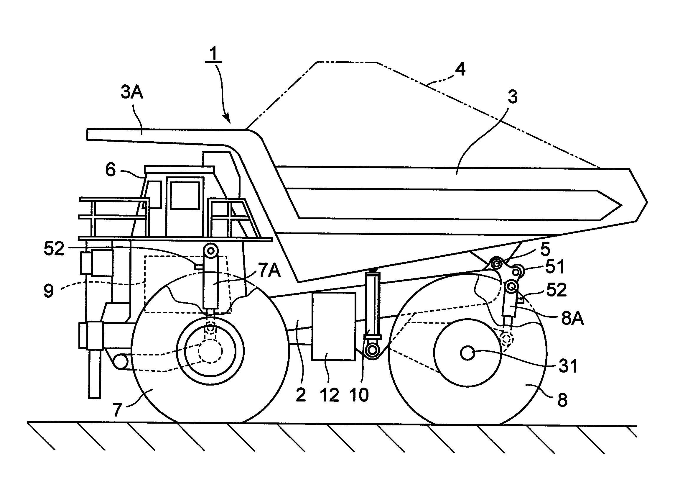
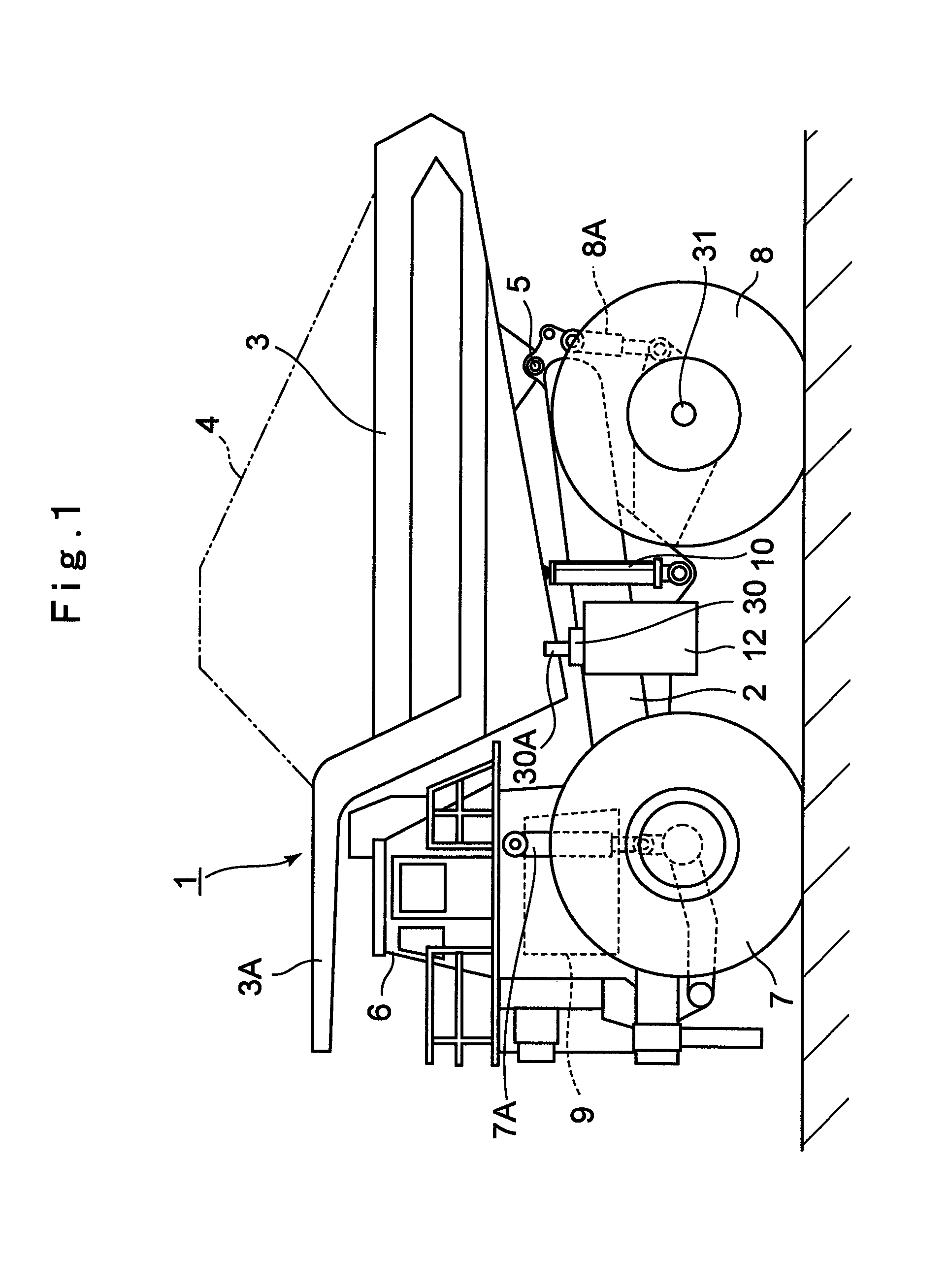
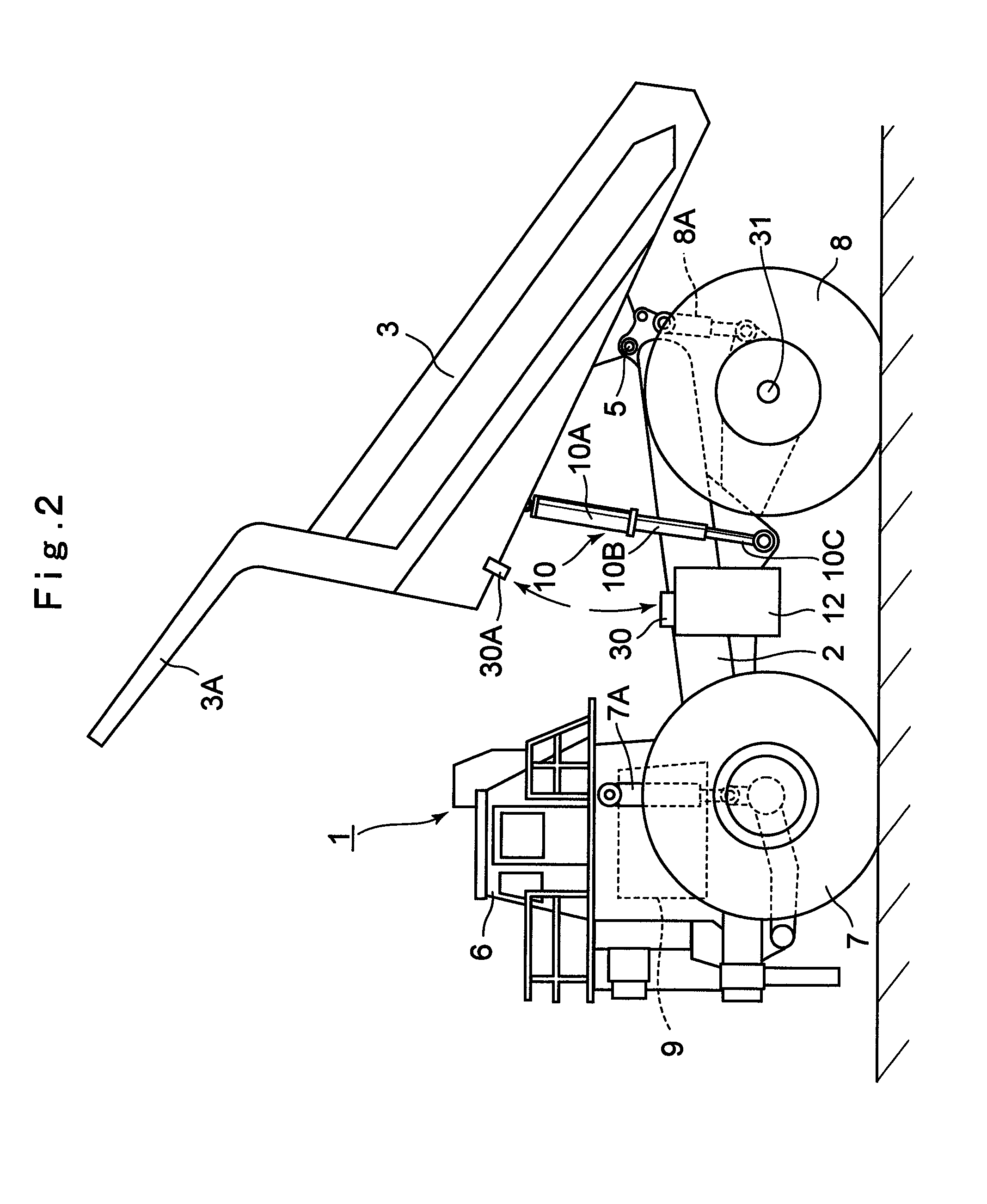
[0074]Referring first to FIGS. 1 through 5, there is shown the present invention. In the drawings, denoted at 1 is a dump truck which is a large-size transporter vehicle. As shown in FIGS. 1 and 2, the dump truck 1 is largely comprised of a vehicle body 2 forming a rigid frame structure and a vessel 3 serving as a loading platform which is tiltably (liftably) mounted on the vehicle body 2.

[0075]Further, the vessel 3 is formed as a large-size container whose overall length reaches as much as 10 to 13 meters to load a large volume of heavy objects to be transported such as crushed stones or other similar objects (hereafter referred to as the crushed stones 4). Its rear side bottom portion is tiltably coupled to a rear end side of the vehicle body 2 by using a connecting pin 5. Further, protectors 3A are projected forward from a front top of the vessel 3 in such a way as to cover from upper side of a cab 6, which will be described hereinafter.

[0076]Namely, the bottom side of the vessel...

second embodiment

[0155]In the case of the second embodiment, jumping motions of the vessel 3 are prevented or suppressed by the controller 42 according to the anti-jumping control of FIG. 9.

[0156]Namely, an anti-jumping control procedure is started with reading in a tilt angle (angle θ) of the vessel 3 from the angle sensor 41 in Step 11. In next Step 12, a judgment is made as to whether or not the angle θ of the vessel 3 is larger than the predetermined reference angle θa, namely, whether or not the vessel 3 is sitting down on the vehicle body 2. In case the judgment in Step 12 is “NO”, it is judged that the vessel 3 is sitting down on the vehicle body 2 and is not in a jumping motion, and the control goes back to repeat Step 11.

[0157]On the other hand, in case the judgment in Step 12 is “YES”, it is judged that the vessel 3 is seated off the vehicle body 2 and there are possibility of a jumping motion occurring, and the control proceeds to next Step 13 to read in a vehicle speed V of the dump truc...

third embodiment

[0160]Now, turning to FIGS. 10 to 12, there is shown the present invention. This third embodiment has a feature in that it is adapted to conduct a control of a loading platform, further taking into consideration a loadage factor of the vehicle body. In the following description of the third embodiment, those component parts which are identical with a counterpart in the foregoing first embodiment are simply designated by the same reference numeral or character to avoid repetitions of similar explanations.

[0161]In the drawings, indicated at 51 is an angle sensor employed as a platform condition detecting means. This angle sensor 51 is substantially of the same build as the angle sensor 41 in the foregoing second embodiment, and mounted to the rear of the vehicle body 2 at a position in the vicinity of a connecting pin 5. The angle sensor 51 is adapted to detect a tilt angle of the vessel 3 relative to the vehicle body 2, i.e., a tilt angle θ as exemplified in FIG. 7, and output a corr...


PUM


Abstract

Detection signals from lever sensor (29), sit-down sensor (30) and vehicle speed sensor (31) are read into a controller (32). A control signal is produced by the controller (32) to switch a directional control valve (20) of a control valve unit (16) instantly from a floating position (c) to a neutral position (a) and to switch another directional control valve (21) from a neutral position (a) to a lowering position (d) when a dump truck (1) is in travel with the directional control valve (20) of the control valve unit (16) is switched in the floating position (c). Whereupon, a hoist cylinder (10) is contracted by a hydraulic pressure force to hold a vessel (3) in a sit-down position on a vehicle body (2), thereby preventing the vessel (3) from shaking movements like floating up while the dump truck (1) is in travel.

Description

TECHNICAL FIELD[0001]The present invention relates to a transporter vehicle such as a dump truck which is suitably used in transporting crushed stones excavated from such as an open-pit stone, a stone quarry, a mine, or dug earth and sand or the like.BACKGROUND ART[0002]In general, a large-size transporter vehicle called a dump truck has a liftable vessel (loading platform) on a frame of a vehicle body, and carries and transports objects to be transported such as crushed stones or earth and sand or the like to an unloading site or a cargo collection site of, for instance, an exit port close to a coast in a state in which the objects to be transported are loaded in a large quantity on the vessel (e.g., see Japanese Patent Laid-Open No. 2001-105954).[0003]A transporter vehicle of this type according to the prior art is comprised of a vehicle body capable of self traveling; a loading platform which is provided on the vehicle body in such a manner as to be capable of being tilted (lifte...

Claims


Application Information

Patent Timeline
Patent Type & Authority Patents(United States)
IPC IPC(8): B60P1/16
CPCB60P1/162
Inventor NABESHIMA, YOSHIFUMIYAGYU, TAKASHISASAKI, TAKASHIMINOSHIMA, TOSHIKAZU
Owner NIHON KENKI CO LTD
Learn More