
Hook for detection of chain sling failure

a chain sling and hook technology, applied in the field of elongated flexible members, can solve the problems of inconvenient use, slings used with the utmost care can be damaged, slings may be defective, and slings may be damaged, etc., to achieve the effect of convenient us

Inactive Publication Date: 2011-10-04
MACHINING & WELDING BY OLSEN
View PDF21 Cites 1 Cited by
  • Summary
  • Abstract
  • Description
  • Claims
  • Application Information

AI Technical Summary

Benefits of technology

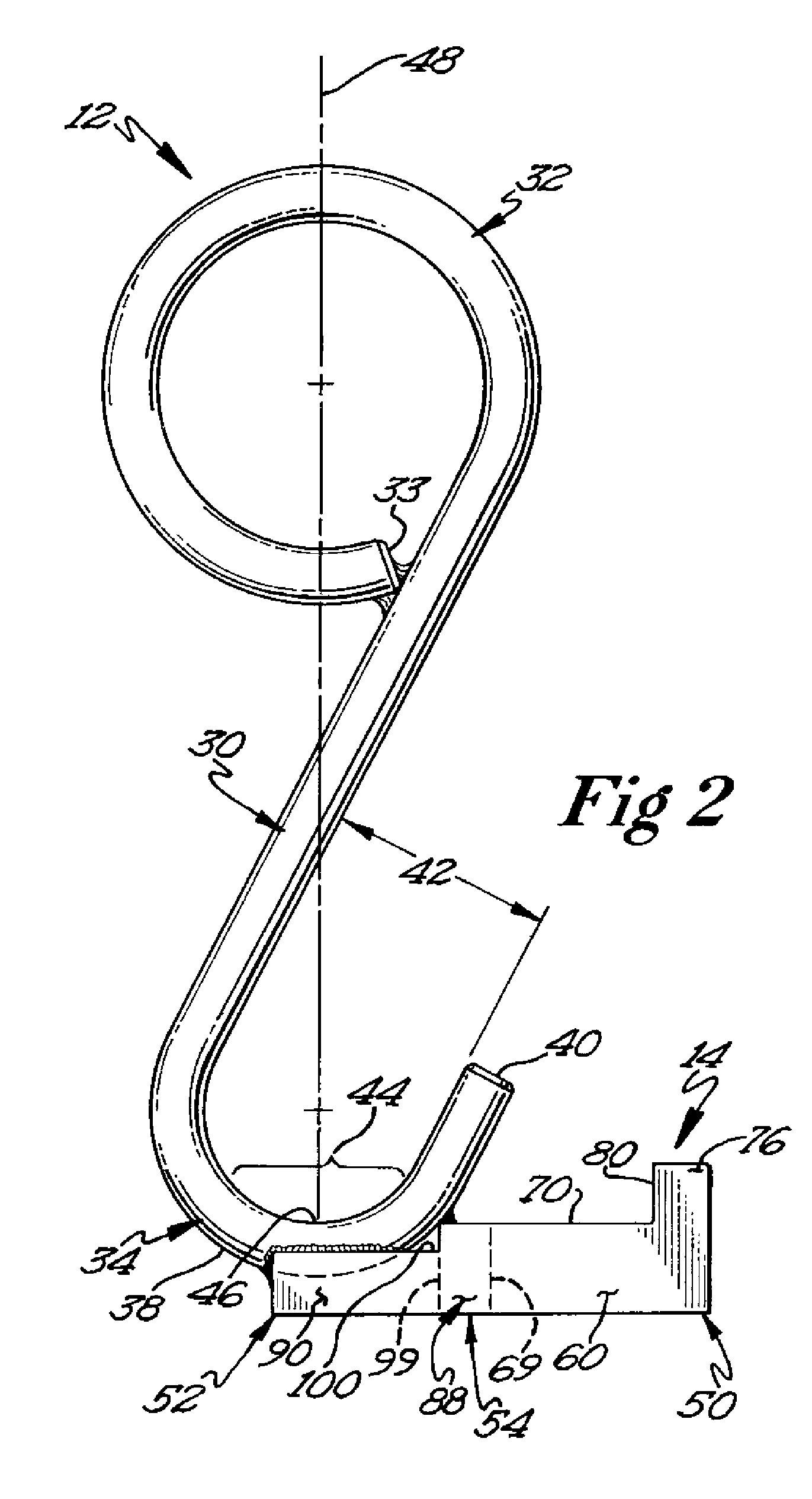
In one embodiment, an apparatus for evaluating the physical condition of an elongated lifting member includes a body with an upper section, a main section, and a lower section. The lower section includes a cradle member that has a support zone that is configured to engage an inwardly facing surface at an end of a sling. A bracket attached to the body includes a measuring device engagement section that precisely positions a tape measure so that its indexing mark is at the same elevation as the upper, inner facing surface of a link that is positioned on the cradle member. In a preferred method of use, the apparatus is attached to a suitable support so that it is suspen

Problems solved by technology

Because slings are often used in harsh, industrial conditions they can be inadvertently or unintentionally damaged.
Even a sling used with the utmost of care can, over time, become nicked, cracked, stretched, bent, corroded, or otherwise altered from its original state.
These conditions can be the result of overloading, improper storage, interaction with sharp corners, dragging along a floor or an abrasive surface, kinking or twisting, shock loading, hostile environments such as excessive heat or cold, chemicals, weld spatter, etc.
Because of the consequences of using defective slings can be catastrophic, the government, through the occupational safety and health administration (OSHA), has mandated that slings be inspected.
However, there are situations in which a sling may be defective, though not visibly so.

Method used


Image

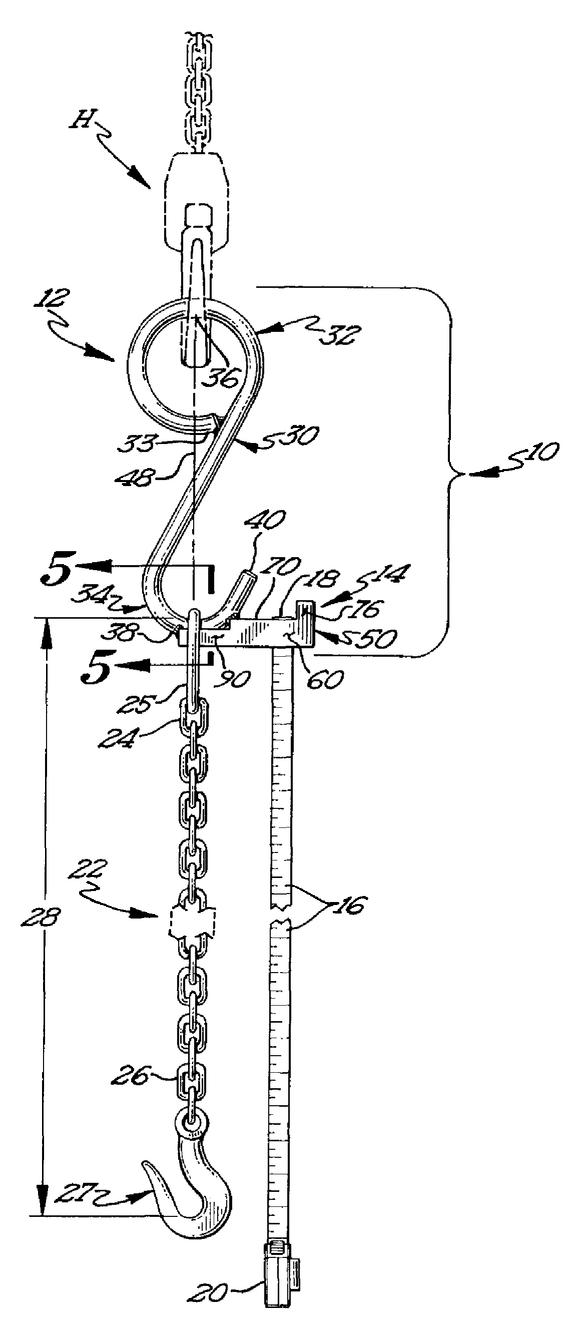
  • Hook for detection of chain sling failure
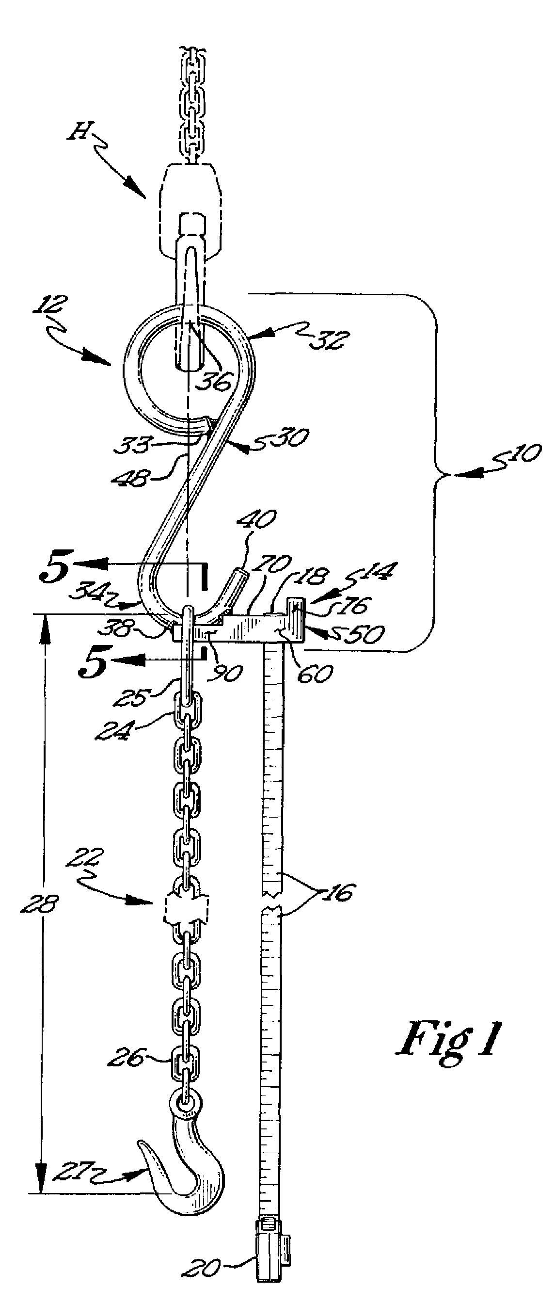
  • Hook for detection of chain sling failure
  • Hook for detection of chain sling failure

Examples


Embodiment Construction

A preferred embodiment of the apparatus 10 as it is being used to evaluate a flexible lifting member is illustrated in FIG. 1. The apparatus 10 is suspended by a vertical support, preferably an adjustable hoist “H” that is equipped with a suitable lifting hook. The apparatus 10 comprises an elongated body 12 and a bracket 14 that is attached to the elongated body 12. A measuring device 16 is received and retained by the bracket 14. The measuring device 16 is of the type that includes an end that is able to be engaged by the bracket. Preferably, the measuring device 16 includes an end with a tang or catch 18 that has an extension that is perpendicular to the plane of the measuring device. More preferably, the measuring device 16 is a flexible, metallic, rule that is received within a protective housing 20 when not in use.

An elongated flexible member 22 that is to be evaluated is connected to the elongated body 12 of the apparatus 10. The elongated flexible member 22 includes a first ...


PUM


Abstract

An apparatus for evaluating the condition of a lift sling. The apparatus includes a body with an upper section and a lower section. The lower section includes a cradle member with a load bearing surface that engages an inner surface of a connecting link at one end of a sling. The apparatus includes an engagement section that receives and positions the end of a measuring device so that it is in tangential alignment with the load bearing surface of the cradle member. In use, one end of a sling is positioned on the load bearing surface of the cradle member and one end of a measuring device is positioned on the engagement section of the apparatus. The apparatus is then raised so that the sling and the measuring device are hanging freely. The reach of the sling is then measuring using the measuring device.

Description

BACKGROUNDThis application relates generally to elongated, flexible members that are used to lift and / or suspend and move heavy and / or bulky objects. More particularly, this application relates to lift slings. Even more particularly, this application relates to an apparatus and method of evaluating the physical condition of a lift sling.In many industries, large and / or heavy objects must be moved from one position to another position, or be lifted to a different elevation, or be loaded onto another object. For objects that are too large, bulky or heavy to be lifted by hand, machines such as cranes or hoists are commonly used. Such machines are usually provided with a cable that is connected to a sheave block or a hook. Often, the sheave block or hook cannot be connected directly to the object to be lifted and instead requires an additional member that is interposed between the sheave block or hook and the object. The additional member is known as a sling. The sling can take differen...

Claims


Application Information

Patent Timeline
IPC IPC(8): G01B3/10
CPCB66C1/125B66C13/16F16G17/00G01B3/1056G01B3/11
Inventor CAMP, DAVIDYOUNG, DARIN
Owner MACHINING & WELDING BY OLSEN
Learn More