
Retractable platform device for use with subway trains and associated method

a platform device and subway technology, applied in railway stations, railway components, ways, etc., can solve the problems of extreme lack of privacy and personal space, commuters' inconvenience, and commute by train or subway, and achieve the effect of reliable safety and convenient transportation

Active Publication Date: 2011-09-20
MAYSONET IGNACIO
View PDF9 Cites 18 Cited by
  • Summary
  • Abstract
  • Description
  • Claims
  • Application Information

AI Technical Summary

Benefits of technology

[0022]In one embodiment, each of the protective guide rails has a longitudinal length registered parallel to the linear travel path of the loading platform for maintaining the loading platform at a substantially stable position during repeated reciprocating movement.
[0023]For any hurried commuter—and especially for those elderly or mobility-restricted commuters for whom these transitions are a particular obstacle—the retractable platform device would provide a convenient, reliable safety bridge between train and platform, platform and train.

Problems solved by technology

Still, with all the news about road-rage, traffic jams, and the mounting hassles of the commuter lifestyle, we may forget that millions of Americans commute in another manner—by train.
Then again, commuting by train or subway does have its downside.
For subway commuters, this lack of privacy and personal space is extreme, as one is frequently shoulder-to-shoulder, standing in a closely packed crowd of fellow riders.
On trains, one's seatmate is often a stranger, and not always a polite or agreeable one.
And then there is the rush out the doors when the train reaches the platform or station—“people pushing, people shoving,” as one rock-n-roll song put it, “on the 8:15 into the city.” On top of all this, there is the very real hazard involved in actually stepping off the train and onto the platform.
You have to consciously step out, or risk falling between the train and the concrete—a mistake that could be the ruin of your day, certainly, if not your life.
Scrambling to get aboard a train, or attempting to get off at the station, a passenger frequently finds himself or herself in an anxious, distracted state of mind—a state more likely to lead to a potentially catastrophic misstep.

Method used


Image

  • Retractable platform device for use with subway trains and associated method
  • Retractable platform device for use with subway trains and associated method
  • Retractable platform device for use with subway trains and associated method

Examples


Embodiment Construction

[0034]The present invention will now be described more fully hereinafter with reference to the accompanying drawings, in which a preferred embodiment of the invention is shown. This invention may, however, be embodied in many different forms and should not be construed as limited to the embodiment set forth herein. Rather, this embodiment is provided so that this application will be thorough and complete, and will fully convey the true scope of the invention to those skilled in the art. Like numbers refer to like elements throughout the figures.

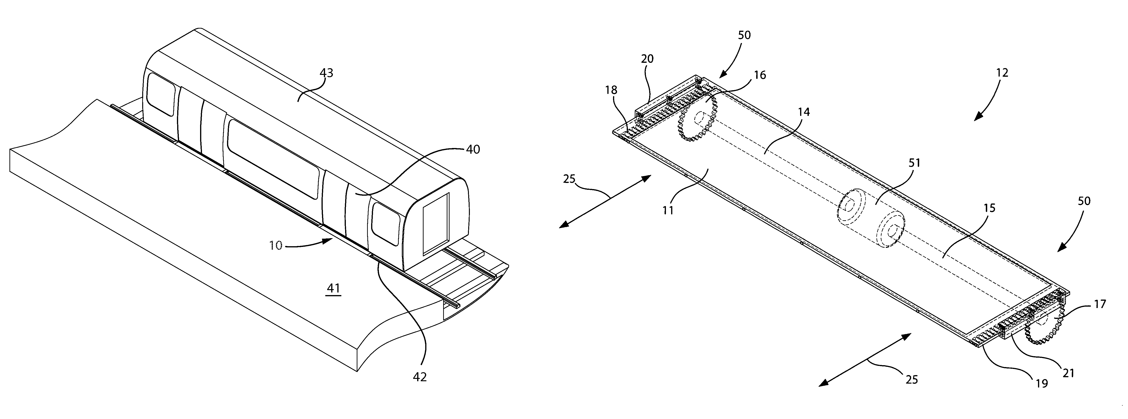
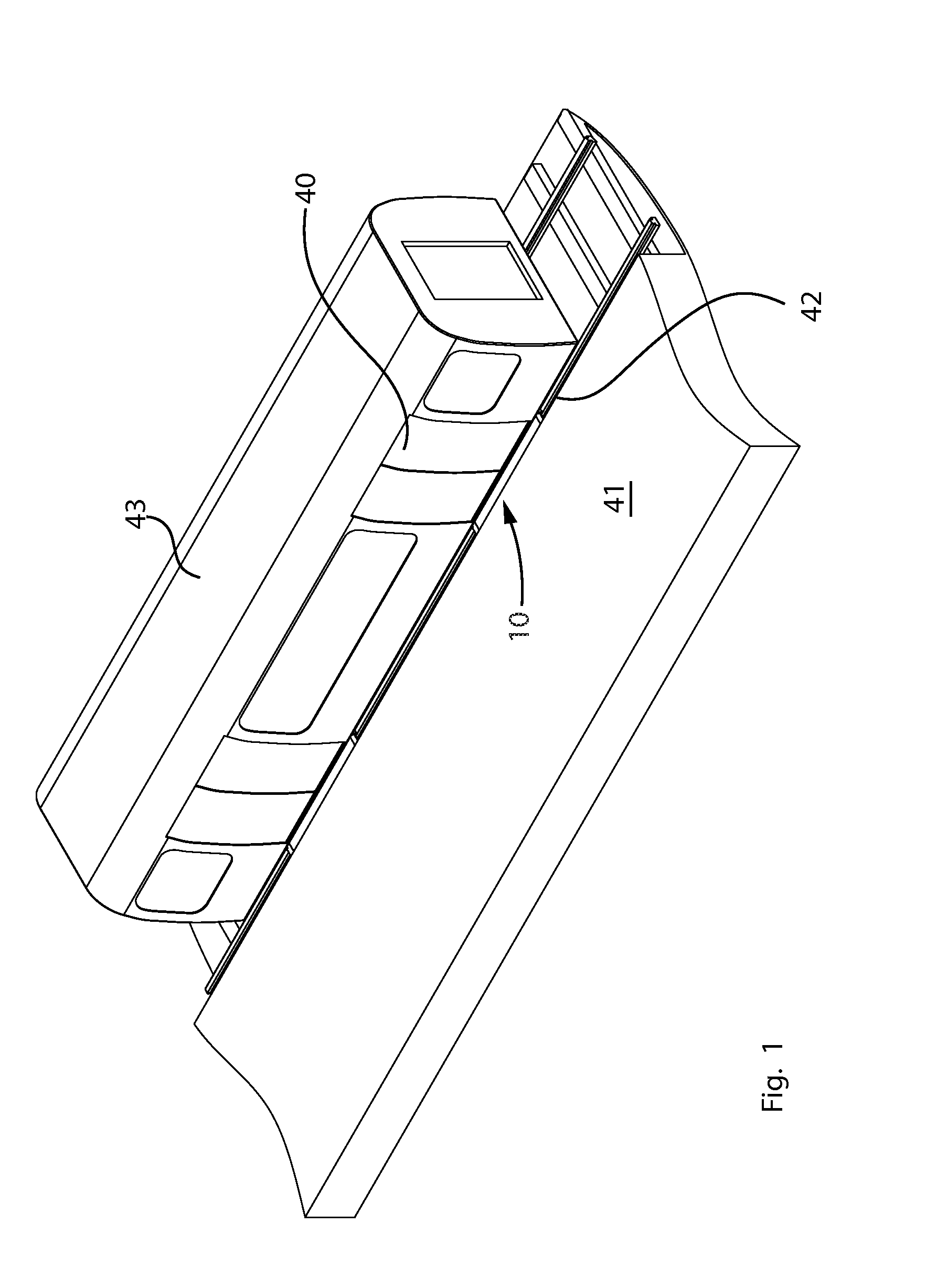
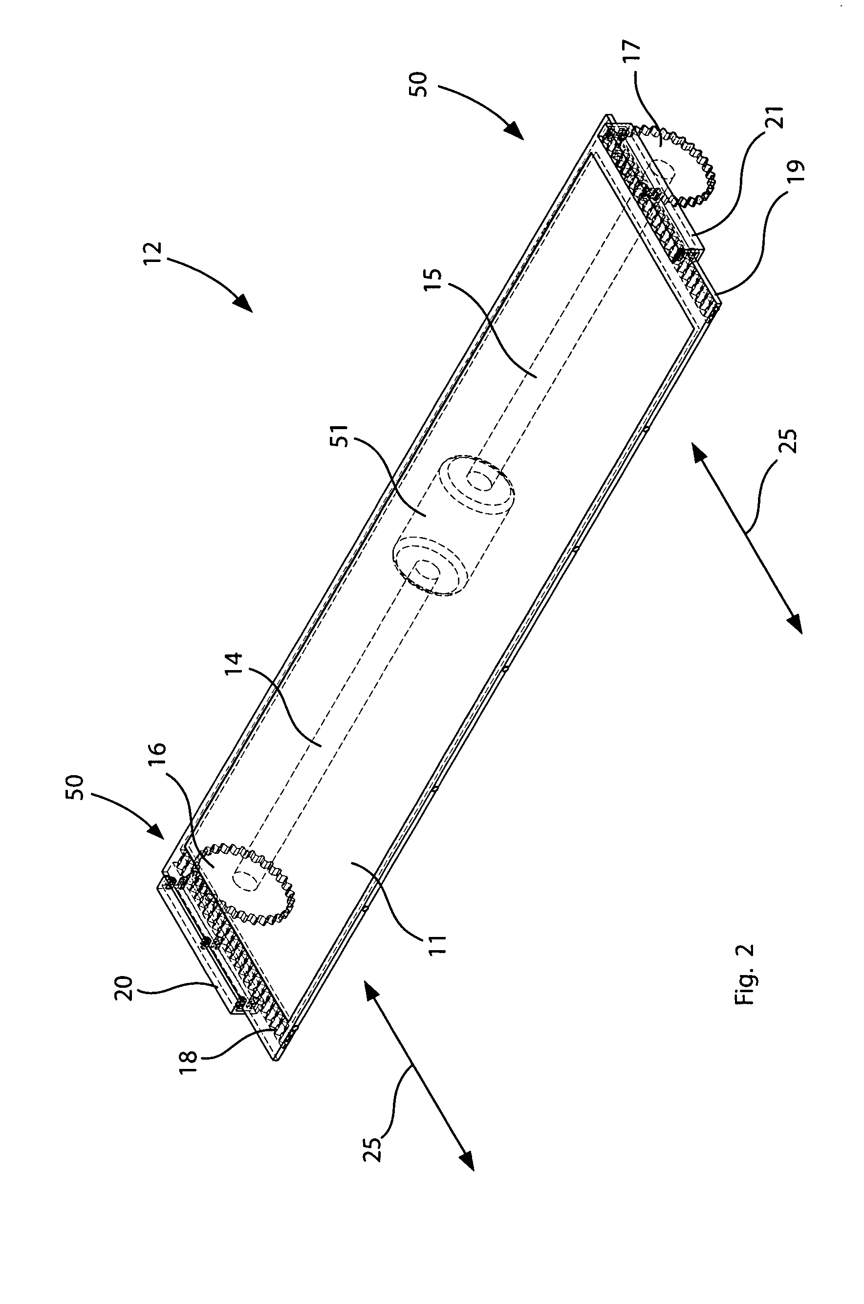
[0035]The device of this invention is referred to generally in FIGS. 1-6 by the reference numeral 10 and is intended to provide an automated platform retracting device 10 for selectively bridging a gap 42 between a train door 40 and a station platform 41 during passenger loading and unloading procedures. It should be understood that the retractable platform device 10 may be used to bridge the gap between many different types of commuter train...


PUM


Abstract

The device would be a metal or heavy-duty plastic retractable loading platform, designed to bridge the gap between the train car and the station platform. When not in use, the retractable platform would be retracted into a position of concealment beneath the door(s) of the train car. At the station, the device would move outward, either abutting or overlapping the station platform, just prior to the train door(s) opening.

Description

CROSS REFERENCE TO RELATED APPLICATIONS[0001]This application claims the benefit of U.S. Provisional Application No. 61 / 069,624, filed Mar. 17, 2008, the entire disclosures of which are incorporated herein by reference.STATEMENT REGARDING FEDERALLY SPONSORED RESEARCH OR DEVELOPMENT[0002]Not Applicable.REFERENCE TO A MICROFICHE APPENDIX[0003]Not Applicable.BACKGROUND OF THE INVENTION[0004]1. Technical Field[0005]This invention relates to retractable platforms and, more particularly, to an automated retractable platform device for bridging a gap between a train and a station platform during passenger loading and unloading procedures.[0006]2. Prior Art[0007]America in the 21st century is a nation of commuters. Most of us work someplace outside the home, and for most of us, that place lies somewhere down the highway. For commuters who live in the suburbs or, increasingly, the farther removed “exurbs,” the commute can be extreme. It is not uncommon for a person employed in San Francisco ...

Claims


Application Information

Patent Timeline
Patent Type & Authority Patents(United States)
IPC IPC(8): B61D47/00B61D23/00
CPCB61B1/00
Inventor MAYSONET, IGNACIO
Owner MAYSONET IGNACIO
Learn More