RF module with a housing with spring loaded connectors and a strain relief extending rearward of the housing
a technology of rf connectors and housings, which is applied in the direction of coupling devices, two-pole connections, and coupling devices. it can solve the problems of contact damage, the rf connectors' mating ends being tilted or rotated within the housing, and the contact axes of the connectors not being properly aligned with one another
- Summary
- Abstract
- Description
- Claims
- Application Information
AI Technical Summary
Problems solved by technology
Method used
Image
Examples
Embodiment Construction
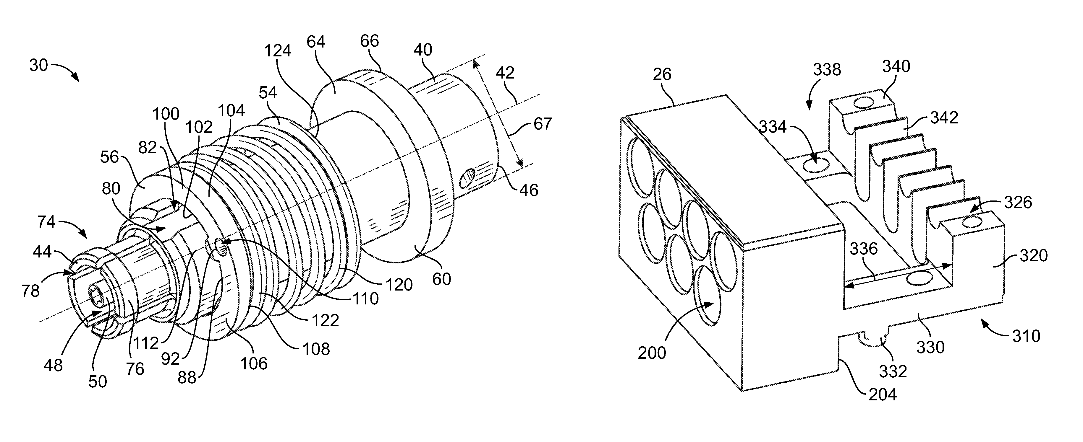
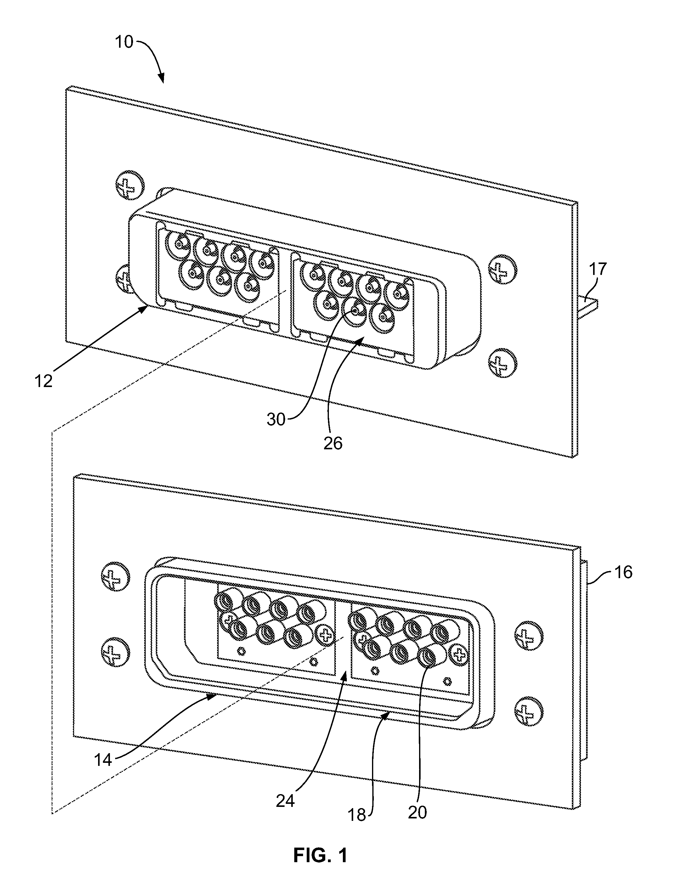
[0017]FIG. 1 illustrates an electrical connector system 10 including an RF module12 and an electrical connector assembly 14 formed in accordance with an exemplary embodiment. FIG. 1 shows front perspective views of both the RF module 12 and the electrical connector assembly 14, which are configured to be mated together along the phantom line shown in FIG. 1. In an exemplary embodiment, the electrical connector assembly 14 defines a motherboard assembly that is associated with a motherboard 16. The RF module 12 defines a daughtercard assembly that is associated with a daughtercard 17.
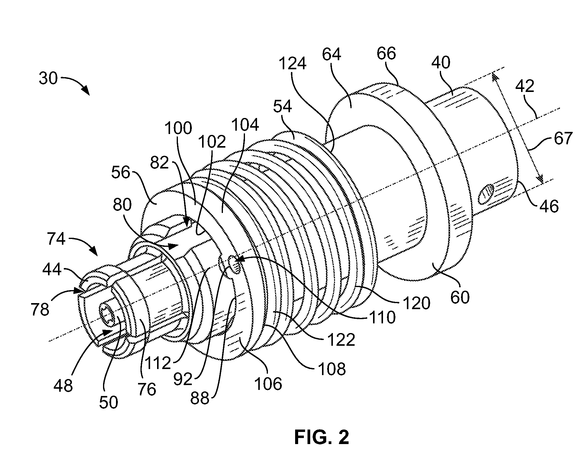
[0018]The electrical connector assembly 14 includes a housing 18 and a plurality of electrical connectors 20 held within the housing 18. Any number of electrical connectors 20 may be utilized depending on the particular application. In the illustrated embodiment, seven electrical connectors 20 are provided in two rows. The electrical connectors 20 are cable mounted to respective coaxial cables 22 (shown ...
PUM
 Abstract
Description
Claims
Application Information
 - R&D
- Intellectual Property
- Life Sciences
- Materials
- Tech Scout
- Unparalleled Data Quality
- Higher Quality Content
- 60% Fewer Hallucinations
Browse by: Latest US Patents, China's latest patents, Technical Efficacy Thesaurus, Application Domain, Technology Topic, Popular Technical Reports.
© 2025 PatSnap. All rights reserved.Legal|Privacy policy|Modern Slavery Act Transparency Statement|Sitemap|About US| Contact US: help@patsnap.com


