Reel

a technology of reels and reel gears, applied in the field of reels, can solve the problems of difficult to uniformly measure the height of the engaging portion, and achieve the effect of accurately welding

Active Publication Date: 2011-08-16
FUJIFILM CORP
View PDF14 Cites 1 Cited by
  • Summary
  • Abstract
  • Description
  • Claims
  • Application Information

AI Technical Summary

Benefits of technology

[0007]The present invention provides a reel having an engaging portion that can accurately engage with a braking member.
[0010]However, in accordance with the first aspect, the engaging portion is formed at the lower flange, and not at the extending portion. Therefore, warping of the welding region and dispersion in the welded amounts do not affect the engaging portion, and the accuracy of the engaging portion (mainly the height from the reel gear) can be made to be uniform. Namely, because the engaging portion is separate from the welding region, dispersion at the time of welding of the engaging portion, of which dimensional accuracy is required, can be eliminated, and the engaging portion can be made to accurately engage with the braking member.
[0012]In accordance with the second aspect, because the extending portion can be formed in an annular shape, the strength of the extending portion can be improved.
[0014]In accordance with the third aspect, the position prescribing portion, that prescribes the heightwise direction and radial direction position of the hub at the time of welding, is formed at the lower flange. Therefore, the hub can be welded accurately with respect to the lower flange.
[0015]As described above, in accordance with the present invention, there is provided a reel having an engaging portion that can accurately engage with a braking member.

Problems solved by technology

In a case in which the engaging portion, with which the braking member engages, is provided at the top surface of the extending portion that is formed at the peripheral edge of the lower end portion of the hub so as to be directed inward, and the lower flange is welded to the bottom surface of this extending portion, it is difficult for the accuracy of the engaging portion (mainly, the height thereof from the reel gear) to be uniform due to warping of the welding region or dispersion in the welded amounts thereof.

Method used


Image

  • Reel
  • Reel
  • Reel

Examples


Embodiment Construction

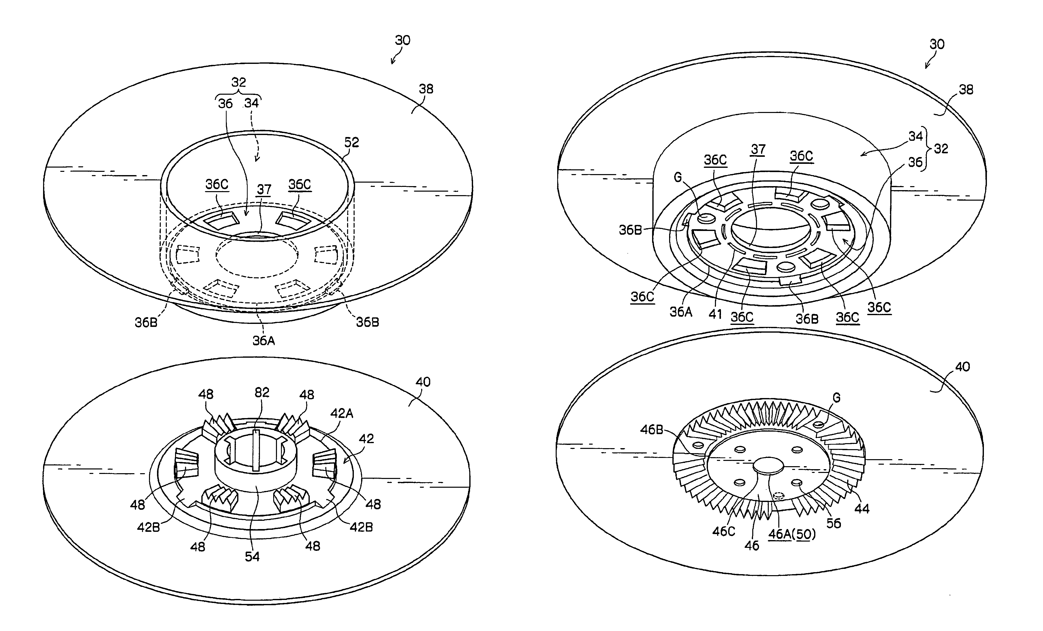
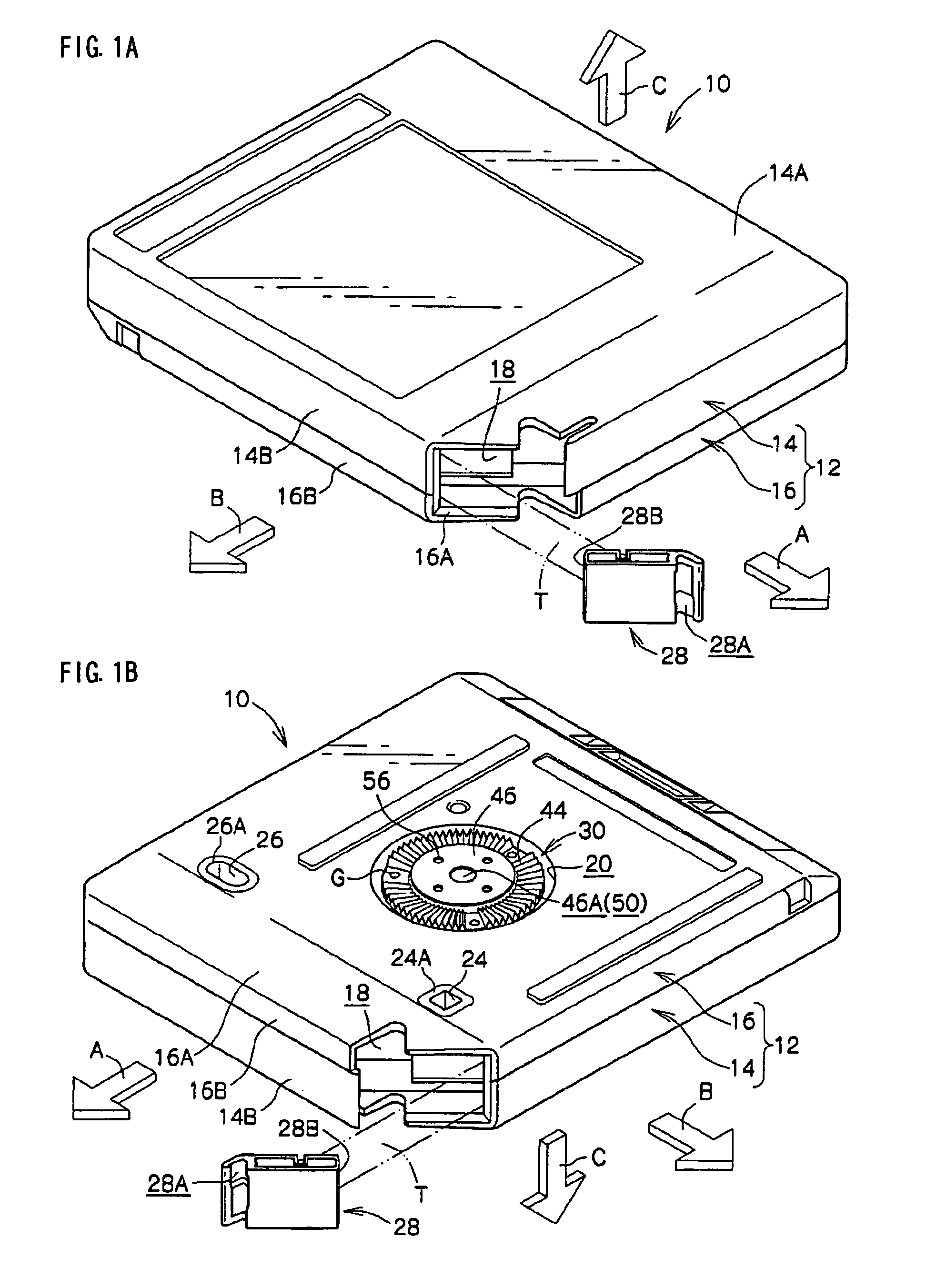
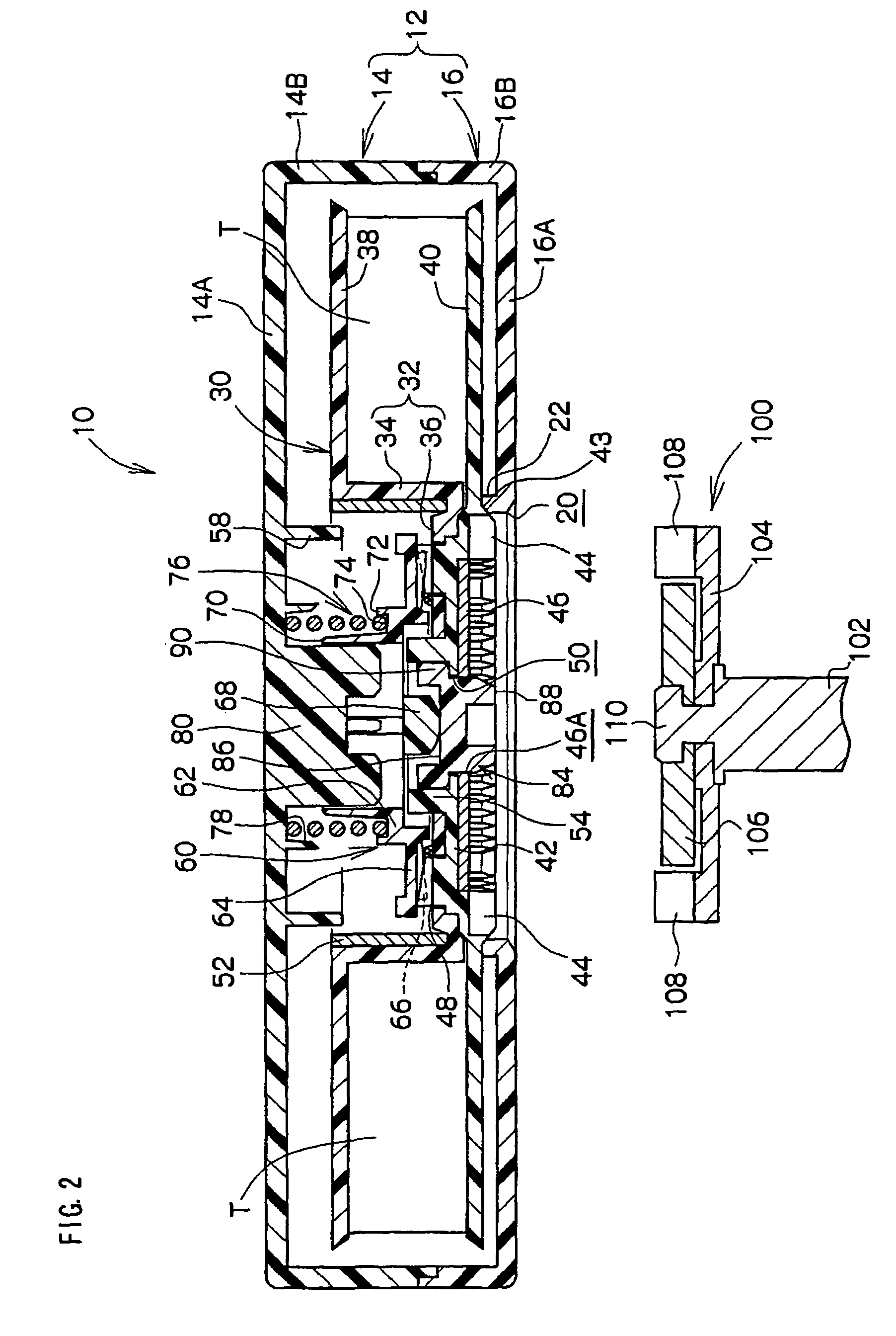
[0029]Hereinafter, a preferred exemplary embodiment of the present invention will be described in detail on the basis of the example illustrated in the drawings. First, the schematic structure of a recording tape cartridge 10, which is equipped with a reel 30 relating to the present exemplary embodiment, will be described. Note that, for convenience of explanation, in FIG. 1A and FIG. 1B, the direction of loading the recording tape cartridge 10 into a drive device is indicated by arrow A, and this is the forward direction (front side) of the recording tape cartridge 10. A direction orthogonal to the direction of arrow A is indicated by arrow B, and this is the right direction (right side) of the recording tape cartridge 10. Further, the direction orthogonal to the direction of arrow A and the direction of arrow B is indicated by arrow C, and this is the upward direction (upper side) of the recording tape cartridge 10 and the reel 30.

[0030]As shown in FIGS. 1A and 1B through FIG. 3, ...


PUM

PropertyMeasurementUnit
timeaaaaaaaaaa
heightaaaaaaaaaa
depthaaaaaaaaaa

Abstract

The present invention provides a reel having an engaging portion that can engage accurately with a braking member. A reel 30 has: a hub 32, an extending portion 36 being formed at a peripheral edge of a lower end portion of the hub 32; an upper flange 38 provided integrally at a peripheral edge of an upper end portion of the hub 32 so as to extend outward; and a lower flange 40 having a floor wall 42 to which a reel plate 46 is fixed, the lower flange 40 being welded to the extending portion 36 of the hub 32. In this reel 30, an engaging portion 48 is formed at the lower flange 40, the engaging portion 48 engaging with a braking member 60 that is held so as to be unable to rotate at the case 12 at times of non-use.

Description

CROSS-REFERENCE TO RELATED APPLICATION[0001]This application claims priority under 35 USC 119 from Japanese Patent Application No. 2007-215027, the disclosure of which is incorporated by reference herein.BACKGROUND[0002]1. Technical Field[0003]The present invention relates to a reel on which is wound a recording tape, such as a magnetic tape or the like, which is used as a recording / playback medium mainly of computers or the like.[0004]2. Related Art[0005]There have conventionally been known recording tape cartridges in which a recording tape, such as a magnetic tape or the like which is used as a data recording / playback medium (for data backup) of computers or the like, is wound on a reel formed of a synthetic resin, and the reel is singly accommodated within a case. Such a recording tape cartridge is provided with a braking member so that, when the recording tape cartridge is not in use (is not loaded in a drive device), the reel does not rotate inadvertently.[0006]As a braking me...

Claims


Application Information

Patent Timeline
Patent Type & Authority Patents(United States)
IPC IPC(8): B65H75/18
CPCG11B23/043G11B23/044G11B23/107B29L2031/704B29C66/81425B29C66/612B29C66/54B29C66/5344B29C66/30223B29C65/7814B29C66/1122B29C65/08B29C66/81431B29C66/81427B29C66/7392B29C66/8322B29C66/24221
Inventor MORI, YASUHIRO
Owner FUJIFILM CORP
Why Eureka
Try Eureka