Birefringent fibers orientation measurement

Inactive Publication Date: 2011-07-26
BOSSA NOVA TECH
View PDF2 Cites 9 Cited by
  • Summary
  • Abstract
  • Description
  • Claims
  • Application Information

AI Technical Summary

Problems solved by technology

However, according to these methods assumptions have to be made about the light that is internally reflected inside the fibers.

Method used


Image

  • Birefringent fibers orientation measurement
  • Birefringent fibers orientation measurement
  • Birefringent fibers orientation measurement

Examples


case i

[0048) is schematically shown in FIG. 4a. The polarization state of the light is not modified while propagating through the fiber. Thus, the internally reflected light component is completely polarized and its polarization state is preserved.

case ii

[0049) is schematically shown in FIG. 4b. The different amount of birefringence experienced by the different polarization components mixed together makes that the light from the internal reflection is circularly polarized.

[0050]If the incident light is polarized otherwise than in cases i) and the internally reflected light will be elliptically polarized.

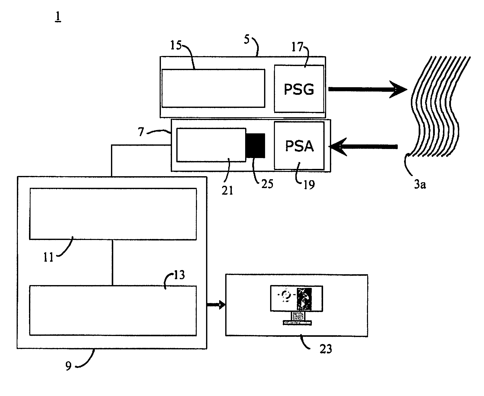
[0051]According to the present disclosure, the orientation of randomly organized birefringent fibers is determined using an apparatus as shown in FIG. 1. As shown in the embodiment of FIG. 2, the light coming from the fiber bundle 3, containing the three components external reflection, internal reflection, and diffusion as described above, is detected by the imaging system 7. The observed light first passes through the PSA 19 before entering the objective lens 25 of the video camera 21. The intensity of the observed light measured this way depends on the state of the polarization analyzer 19. Preferably, the intensity measurement of ...


PUM

PropertyMeasurementUnit
wavelengthaaaaaaaaaa
polarization anglesaaaaaaaaaa
birefringentaaaaaaaaaa

Abstract

Methods and apparatus to determine the orientation of randomly arranged birefringent fibers are disclosed. One method comprises emitting light, creating Ni polarization states of the emitted light, illuminating the birefringent fibers with the emitted light so polarized, thereby generating IRi internal reflection components of the light in the birefringent fibers, observing the light from the illuminated birefringent fibers, creating Oi polarization states of the observed light, forming Ii images of the observed polarized light, each image comprising an information (Ni, Oi, IRi), wherein i=1, 2, . . . , n and n≧3, separating the i-th internal reflection component from the i-th image, and calculating an angle of a neutral axis of the birefringent fibers using the IRi internal reflection components.

Description

CROSS-REFERENCE TO RELATED APPLICATIONS[0001]The present application claims priority under 35 U.S.C. §119(e) to U.S. Provisional Patent Application Ser. No. 61 / 192,702, entitled “Visual appearance measurement method and system for randomly organized birefringent fibers” filed on Sep. 22, 2008 by Nicolas Lechocinski, et al.BACKGROUND[0002]1. Field of the Disclosure[0003]The present disclosure relates generally to an apparatus and a method for determining the orientation of randomly arranged birefringent fibers, such as for example textile fibers and hair.[0004]2. Background Art[0005]Polarization imaging is being used in many applications. In passive imaging, where the illumination is not controlled, i.e., not actively polarized, polarization imaging can be used, for example, to enhance the contrast between human made objects that have a strong polarization signature from the natural background. It also provides information on the shape of the objects. Further, polarization imaging co...

Claims


Application Information

Patent Timeline
Patent Type & Authority Patents(United States)
IPC IPC(8): G01N21/00
CPCG01N21/23G01N21/84G01N2021/8444
Inventor LECHOCINSKI, NICOLASBREUGNOT, SEBASTIENPOUET, BRUNO FRANCOIS
Owner BOSSA NOVA TECH
Why Eureka
Try Eureka