
Apparatus and methods for performing process simulation using a hybrid model

a hybrid model and process simulation technology, applied in the field of process simulation and analysis, can solve the problems of complex geometries of injection molding plastic, significant computational time and computer resources, and complex modeling processes, and achieve the effects of less costly simulations, reduced computational time and computer resources, and negligible impact on accuracy

Active Publication Date: 2011-07-12
MOLDFLOW IRELAND LTD
View PDF57 Cites 12 Cited by
  • Summary
  • Abstract
  • Description
  • Claims
  • Application Information

AI Technical Summary

Benefits of technology

[0022]Simulation of fluid flow within a mold cavity generally requires a representation of the mold cavity or molded component. In one aspect, the invention provides a method for simulating fluid flow that automatically divides a representation of a component and / or mold cavity into at least two portions—a portion in which a simplified analysis may be conducted, and a portion in which a more complex analysis is required. The method then includes performing a hybrid analysis—that is, solving a set of simplified governing equations in the simpler portion and a set of more complex governing equations in the complex portion. This reduces the amount of time and memory required to perform a simulation, without compromising accuracy, since the complex set of equations must be solved only where the geometry of the mold or component is complicated. The simplified analysis may be a 2.5D Hele-Shaw analysis, a 2D analysis, a 1D analysis, or any other kind of analysis in which simplifying assumptions can be made with respect to one or more dimensions and / or other variables.
[0024]The invention provides simulations having greater accuracy than current hybrid schemes. For example, an embodiment of the invention accounts for temperature by incorporating an energy conservation equation in the analysis. Furthermore, the invention allows solution of accurate forms of the mass and momentum conservation equations in the analysis scheme, without requiring simplifying assumptions, as in Equation 1.
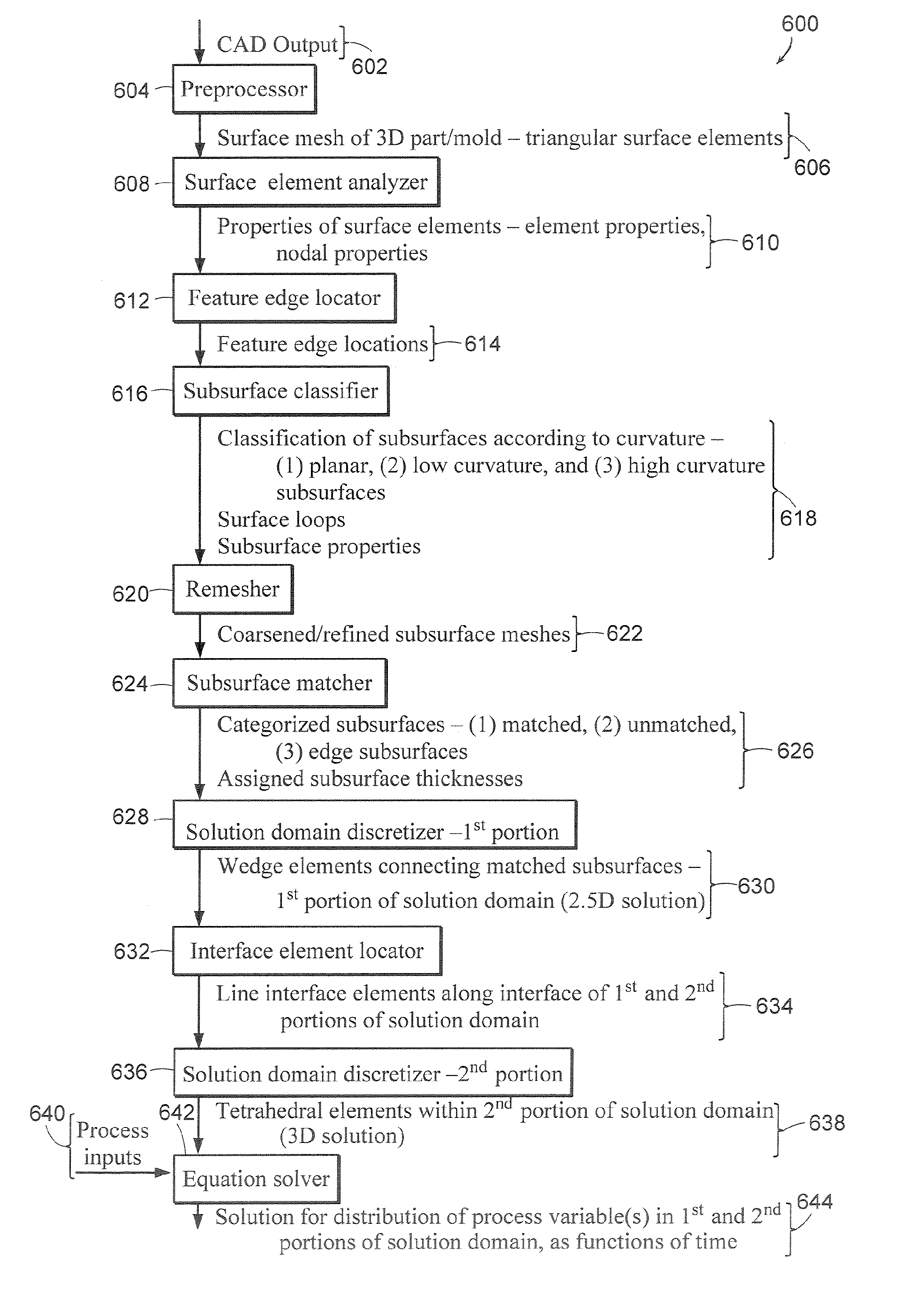
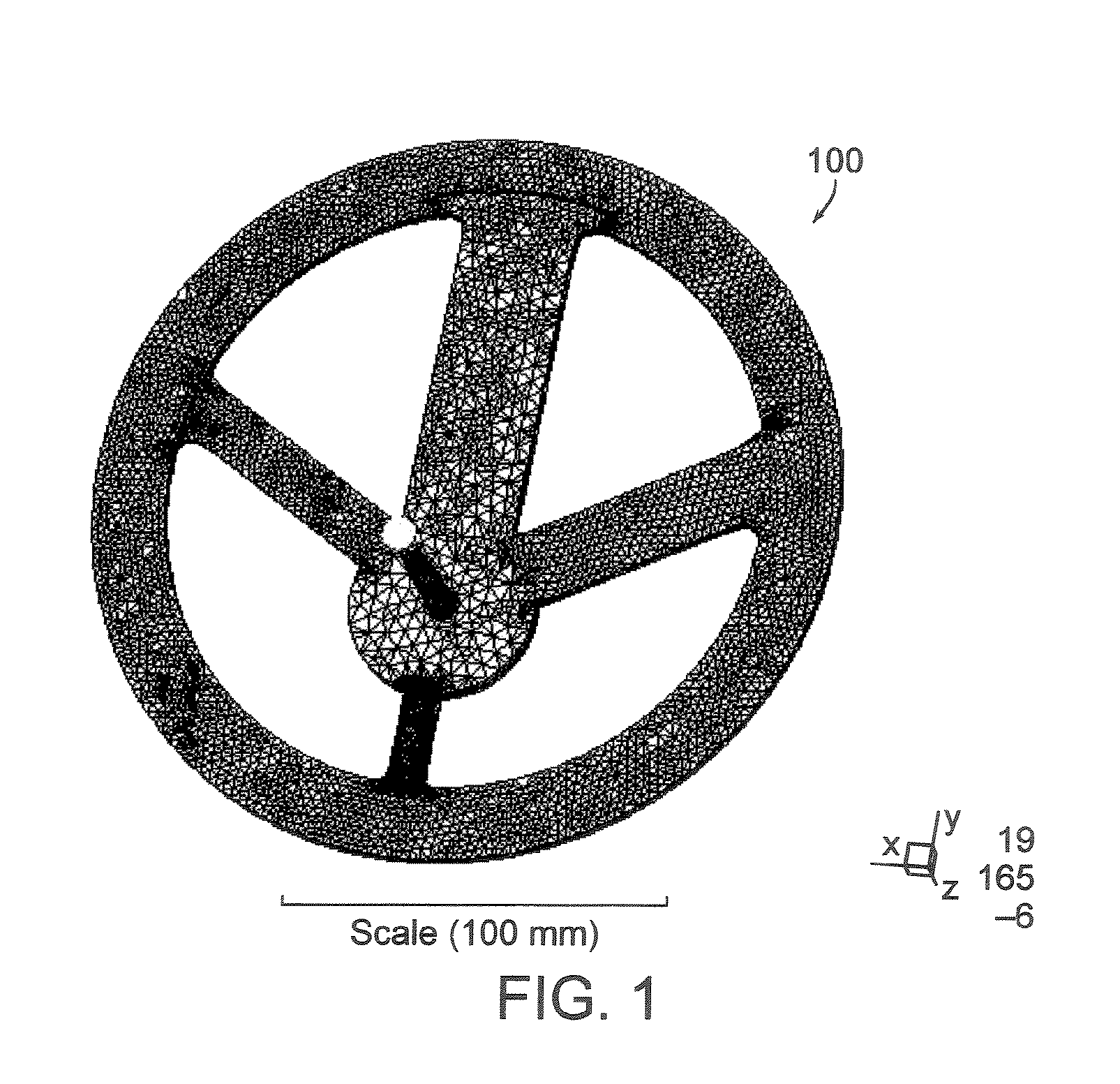
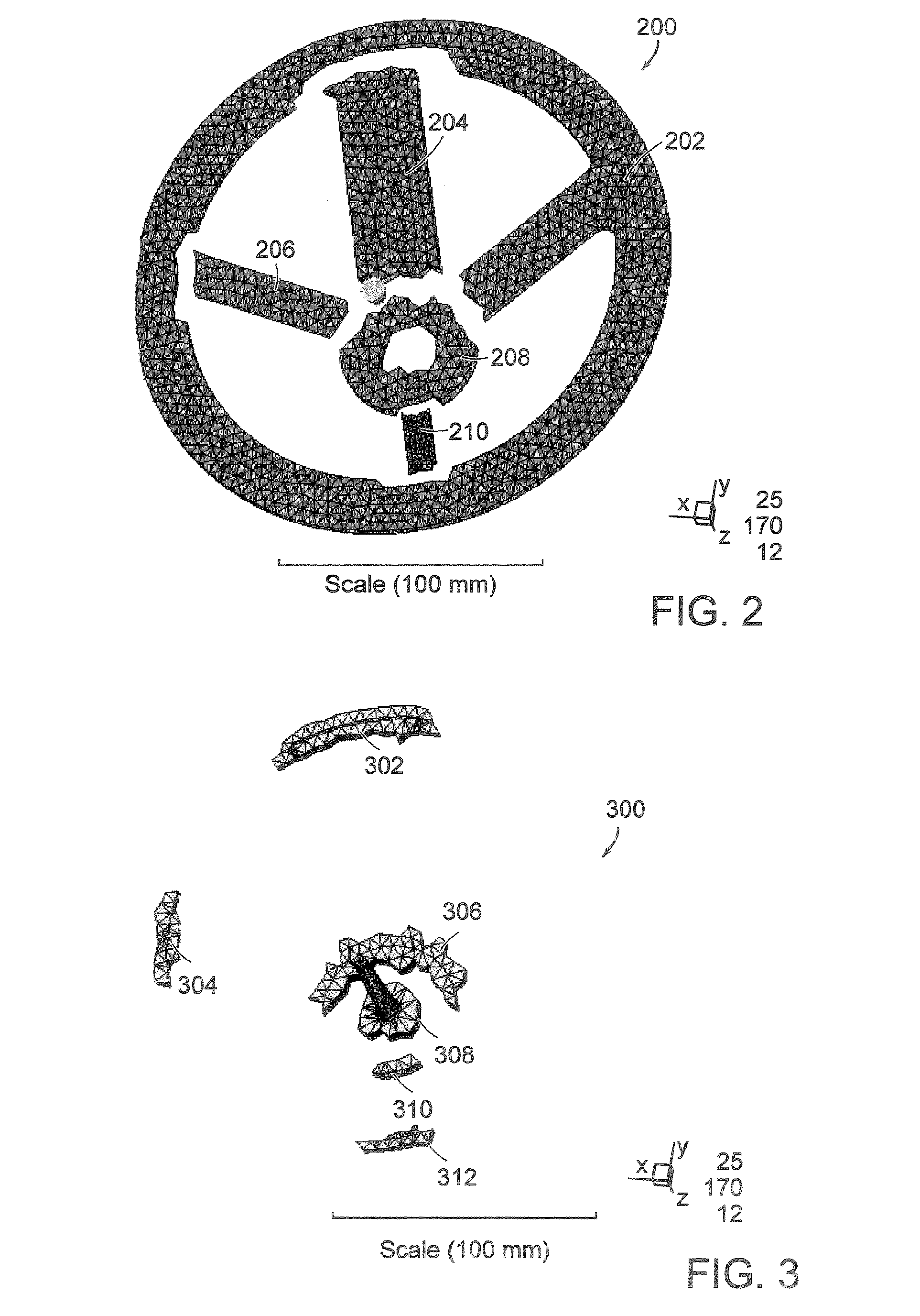
[0026]Methods of the invention are more robust and require less input from skilled technicians than traditional simulation techniques. For example, in one embodiment, the invention uses simple CAD system output to define a surface mesh of a component or mold to be modeled, then automatically divides the mesh into a 2.5D-analysis portion and a 3D-analysis portion via a subsurface matching technique, and automatically discretizes the two portions to form a solution domain in which hybrid analysis is performed. It is not necessary for a technician to decide how to separate a solution domain into 2.5D and 3D analysis portions, since the embodiment performs the separation automatically. In addition to CAD system output, the invention may use any other type of data file conveying a representation of the surface of the component or mold to be modeled. Since the domain is tied to the actual geometry of the component or mold surface, the invention is capable of displaying results directly on the 3D geometry of the component, making interpretation of results more intuitive for a user than schemes which require the creation of a midplane mesh, for example.
[0033]In one embodiment, one or more steps of the method are performed automatically in the sense that they are performed by computer, requiring limited or no input from a skilled technician. For example, in one embodiment, a discretized, hybrid solution domain is produced automatically from a user-provided description of the surface of a component or mold cavity, without requiring additional input from the user. In another example, a discretized, hybrid solution domain is produced automatically from a user-provided description of the surface of a component or mold cavity, where the user also provides (or is prompted to provide) information regarding element aspect ratio, specified edge length (SEL), process model inputs such as boundary conditions and / or initial conditions, and / or other information related to how the solution domain will be used. The production of the solution domain is still automatic, even though a user provides certain specifications, since the separation of the domain into portions and the discretization of the solution domain are subject to internal constraints imposed by the computer-performed method. Certain embodiments provide default values of one or more modeling specifications for which the user is prompted. The default values may or may not be based on the specific component and / or process being modeled. Certain embodiments provide a user the option of providing a modeling specification himself, accepting a pre-determined default value of the modeling specification, and / or using a computer-determined value of the modeling specification based on information about the component and / or process being modeled.

Problems solved by technology

Process and structural analysis in these fields poses significant challenges.
Modeling processes involving components with complex geometries requires significantly more computational time and computer resources than modeling processes involving components with simple geometries.
Also, injection-molded plastic is viscoelastic and may have highly temperature-dependent and shear-dependent properties.
These complexities further increase computational difficulty of process and structural simulations involving plastic components.
Analytical solutions of these equations over complex domains are generally unavailable; thus, numerical solutions must be sought.
However, in components that have thick portions or complex geometries, injected material flows in all three directions, and traditional thin-wall assumptions do not apply, making the 2.5D analysis inadequate.
These models are computationally complex, generally requiring significantly greater computer resources and computation times for process simulation than the simpler 2.5D models.
The generation of a 3D mesh is not trivial, and there is currently no consistent method of automatically generating a suitable 3D mesh for a given application.
However, many of these components also have one or more thick or complex portions in which the 2.5D assumptions do not hold, thereby making the overall analysis inaccurate.
However, the computational complexity of a 3D model is much greater than that of a 2.5D model, thereby increasing the time and computer resources required for analysis.
Additionally, the way a 3D model must be discretized further reduces the efficiency of a 3D process model for a component having thin portions.
The high variability of these properties in at least two directions—temperature across the thickness, and pressure along the length—calls for a very dense mesh with many solution nodes in order to achieve an accurate process simulation, thereby increasing computational complexity.
Thus, the time required for accurate 3D simulation of a typical component containing both a thick and a thin portion may be as much as a day or more and may require significant computer resources, due to the fine discretization required.
The suggested technique does not account for temperature variation and, thus, does not provide accurate results in non-isothermal systems where material properties vary with temperature, as in most injection molding systems.
Furthermore, there does not appear to be a suggestion of how to adapt the technique for the analysis of more complex parts than the examples shown.
The approximation of Equation 1 is more akin to the 2.5D Hele Shaw approximation than full 3D analysis, and Equation 1 does not adequately describe fluid flow in components having thick and / or complex portions, particularly where the thick portion makes up a substantial (nontrivial) part of the component.
Current modeling methods are not robust; they must be adapted for use in different applications depending on the computational complexity involved.
The decisions made in the process of choosing and developing a model for a given component and / or process may well affect the accuracy of the model output.
The process of adapting models to various applications is time-consuming and generally involves significant customization by a highly-skilled technician.

Method used


Image

  • Apparatus and methods for performing process simulation using a hybrid model
  • Apparatus and methods for performing process simulation using a hybrid model
  • Apparatus and methods for performing process simulation using a hybrid model

Examples


Embodiment Construction

[0063]Table 1 lists various symbols used herein and is provided as a convenience for the reader. Entries in Table 1 do not serve to limit interpretation of embodiments of the invention described herein.

[0064]

TABLE 1NotationSymbolDescription∇Gradient operatorαThermal⁢⁢diffusivity:⁢⁢λρcpβExpansivity:1V⁢⁢∂V∂TδKronecker delta{dot over (γ)}Shear rateηViscosityκCompressibility:⁢-1V⁢⁢∂V∂PλThermal conductivityνPoisson's ratioρDensityσStressτStress (deviatoric part)υVelocity{right arrow over (υ)}Velocity vectorυx, υy, υzVelocity componentsωRelaxation factorξFlow ‘conductance’ΔIncrement, i.e., in timestepΛLocally-defined quantityΩDomain∂ΩBoundary of domain, Mold / plastic interfacecpSpecific heatdDistance of (tet) node from model walleElement∂eBoundary of elementg, {right arrow over (g)}Gravity / body-force and gravity / body-force vectorhHalf wall thickness of plastic component / partkCoefficient matrix of elementnUnit normal vectorrLoad vector of elementtTimeAAreaAeArea of elementAeT,AeBTop and bot...


PUM

PropertyMeasurementUnit
thicknessaaaaaaaaaa
bend angleaaaaaaaaaa
edge bend angleaaaaaaaaaa

Abstract

The invention provides an apparatus and methods for performing process simulation and structural analysis using a hybrid model. For example, a method of the invention automatically defines a hybrid solution domain by dividing a representation of a plastic component or mold cavity into two portions—a portion in which a simplified analysis may be conducted, and a portion in which a more complex analysis is required. The method may use as input any form of CAD data that describes the surface of a component or mold. Furthermore, the invention provides methods for simulating fluid flow within a mold cavity by automatically creating a hybrid solution domain, automatically discretizing the domain, and solving for the distribution of process variables within the solution domain.

Description

PRIOR APPLICATIONS[0001]The present application is a continuation application of U.S. patent application Ser. No. 10 / 771,739, filed Feb. 4, 2004, which claims the benefit of U.S. Provisional Patent Application No. 60 / 445,182, filed Feb. 5, 2003, which are hereby incorporated by reference in their entirety.FIELD OF THE INVENTION[0002]This invention relates generally to methods of process simulation and analysis. More particularly, the invention relates to the simulation of injection molding using a multidimensional model.BACKGROUND OF THE INVENTION[0003]Manufacturers use process analysis and structural analysis in designing a wide variety of products, including consumer goods, automotive parts, electronic equipment, and medical equipment. It is often advantageous to simulate or otherwise model a manufacturing process to aid in the development of a particular product. A computer simulation of a manufacturing process may allow accurate prediction of how changes in process variables and...

Claims


Application Information

Patent Timeline
Patent Type & Authority Patents(United States)
IPC IPC(8): G06G7/50B29C45/76G06F17/50
CPCB29C45/7693G06F17/5018G06F2217/41G06F2113/22G06F30/23G06G7/50
Inventor YU, HUAGANGKENNEDY, PETER
Owner MOLDFLOW IRELAND LTD
Learn More