
Spherical projectile reloading system

a projectile reloading and spherical technology, applied in the direction of compressed gas guns, white arms/cold weapons, weapons, etc., can solve the problems of reducing the target profile of users, limiting the number of paintballs a player has available to his or her disposal, and limiting the amount of this type of coverage, etc., to achieve the effect of easy replacement and rapid

Inactive Publication Date: 2011-07-12
HANDEL BRANDON
View PDF35 Cites 5 Cited by
  • Summary
  • Abstract
  • Description
  • Claims
  • Application Information

AI Technical Summary

Benefits of technology

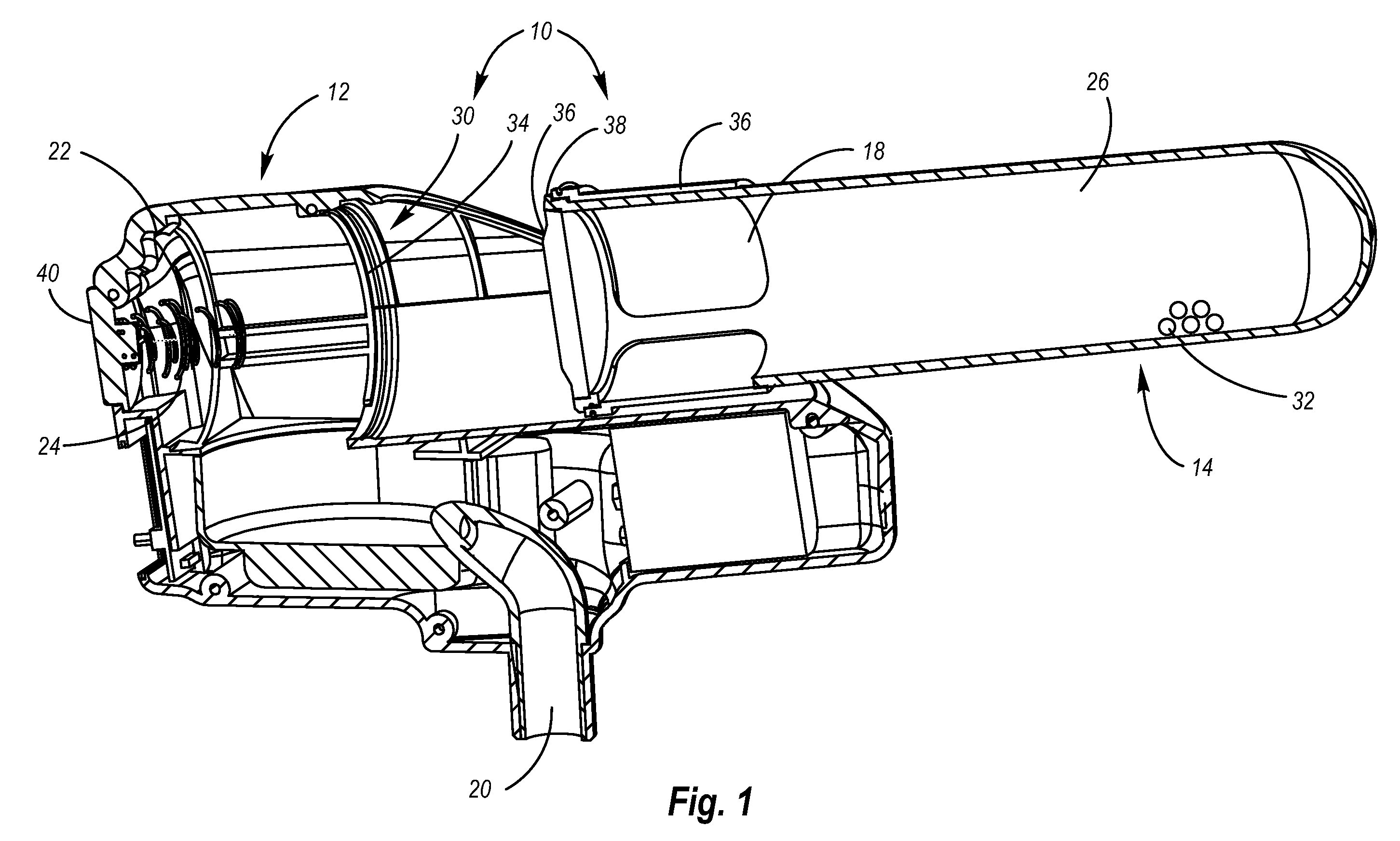
[0006]According to the present invention, the foregoing advantages and objects are obtained by a base unit attached to a spherical projectile propulsion device that is connected to the feed tube of the spherical projectile marker. A base unit is a generally-static attachment to the spherical projectile marker. A spherical projectile marker can be any number of devices that propel spherical objects by pneumatic or mechanical means including, but not limited to, markers used in paintball, airsoft, or law enforcement. Attached to the base unit is a removable cartridge that holds the projectiles to be used. The cartridge is tubular and has a sliding gate. The removable cartridge also holds several paintballs. The cartridge delivers the projectiles to the base unit by gravity feed. The sliding gate keeps the projectiles within the cartridge until the cartridge is connected to the base unit. The cartridge can be replaced easily and rapidly by simply removing the cartridge and replacing it with a new one. The sliding gate that is attached to the cartridge will move open when the cartridge is inserted into the base unit and then will move to close when the cartridge is removed from the base unit.
[0007]In one preferred embodiment of the device, the removable cartridge is generally cylindrical so as to allow the user to quickly insert the cartridge without needing to align the cartridge along the axis of the base unit. The user simply inserts the cartridge into the base unit by aligning the axis of the cylinder with the axis of the opening to the base unit. By using a cylindrical cartridge, the user can quickly load and re-load the base unit using less attention than a system that requires the user to align the cartridge before attaching to the base unit.

Problems solved by technology

The amount of this type of coverage is limited by the amount of paintballs available to the player.
A smaller hopper reduces the user's target profile but limits the number of paintballs a player has available to his or her disposal.
Reloading the base unit provides the user with additional paintballs but also makes the user vulnerable to attack during the refilling process.
First, the reloading process may require the use of two hands to open the hopper and cartridge.
Second, the user must partially divert his or her attention away from the game to the reloading process.
A user who focuses too much on the reloading process may open himself or herself to attacks from other players while players focusing too much on the game may spill and waste a significant portion of their paintballs thereby increasing the frequency of reloading sessions.
Depending on the complexity of the system, problems may also arise from components in the system failing.
Increasing the complexity of the system increases the probability of component failure.
Third, the time it takes to refill the hopper is also time that an avenue of egress remains uncovered by suppression fire.
Failure to properly close the hopper may result in paintballs falling out of the hopper thereby decreasing the number of balls available for attack.

Method used


Image

  • Spherical projectile reloading system
  • Spherical projectile reloading system
  • Spherical projectile reloading system

Examples


Embodiment Construction

[0014]While the invention is susceptible of various modifications and alternative constructions, certain illustrated embodiments thereof have been shown in the drawings and will be described below in detail. It should be understood, however, that there is no intention to limit the invention to the specific form disclosed, but, on the contrary, the invention is to cover all modifications, alternative constructions, and equivalents falling within the spirit and scope of the invention as defined in the claims.

[0015]In the following description and in the figures, like elements are identified with like reference numerals. The use of “or” indicates a non-exclusive alternative without limitation unless otherwise noted. The use of “including” means “including, but not limited to,” unless otherwise noted.

[0016]FIG. 1 and FIG. 3 show a cross sectional view of the quick loading propulsion device 10, which comprises a base unit 12 attached to a projectile propulsion device through base unit co...


PUM


Abstract

A reloading system for dispensing spherical projectiles is disclosed. The reloading system has a removable cartridge that removes from a base unit attached to a spherical projectile device. Upon insertion of the cartridge, a sliding gate on the removable cartridge permits direct feed of the projectiles to the projectile device. An ejection mechanism releases the cartridge for insertion of another cartridge.

Description

FIELD OF THE INVENTION[0001]The present invention generally relates to quick reloading systems for round projectiles and more particularly to the quick reloading systems for paintball markers.BACKGROUND OF THE INVENTION[0002]In many different situations, luck is simply opportunity meeting preparation. In paintball, opportunities are created when your opposing force becomes vulnerable. Preparation is reducing your own vulnerabilities and defining tactics and strategies that reduce the probability of the opponent taking advantage of your vulnerabilities.[0003]In the game of paintball, players may fire several hundred paintballs in a matter of minutes. Covering avenues of egress effectively so as to dissuade opposing teammates from attack may require a consistent barrage of paintballs. The amount of this type of coverage is limited by the amount of paintballs available to the player. In some settings, a large hopper may provide an adequate supply but the larger hopper increases the tar...

Claims


Application Information

Patent Timeline
Patent Type & Authority Patents(United States)
IPC IPC(8): F41B11/02
CPCF41A9/64F41B11/55
Inventor HANDEL, BRANDON
Owner HANDEL BRANDON
Learn More