Bi-directional seaming machine

a seaming machine and bi-directional technology, applied in the field of seaming machines, can solve the problems of only being used for seaming devices, more unwieldy to handle, and relatively slow movement of the carriage back to its starting position

Active Publication Date: 2011-07-12
MILLER WELDMASTER CORP
View PDF10 Cites 21 Cited by
  • Summary
  • Abstract
  • Description
  • Claims
  • Application Information

AI Technical Summary

Problems solved by technology

As will be appreciated, the larger the sheet becomes, the more unwieldy it is to handle.
However, the seaming device is only being used for seaming when the carriage is moving in a single direction.
The relatively slow movement of the carriage back to its starting position is lost time in which no welding occurs.
Considering the fact that some seams may be several hundred feet long, this lost time may be considerable.
After each segment of sheet material is seamed to the previous one, additional sheet material must be moved off of the table or work surface and gradually piles up on the floor, often in disarray.
Furthermore, material hanging off of the table or an elevated work surface pulls on the material atop the table and adds to the difficulty of aligning the material for a subsequent seaming operation.
In short, the process is relatively time consuming and labor intensive.

Method used


Image

  • Bi-directional seaming machine
  • Bi-directional seaming machine
  • Bi-directional seaming machine

Examples


Embodiment Construction

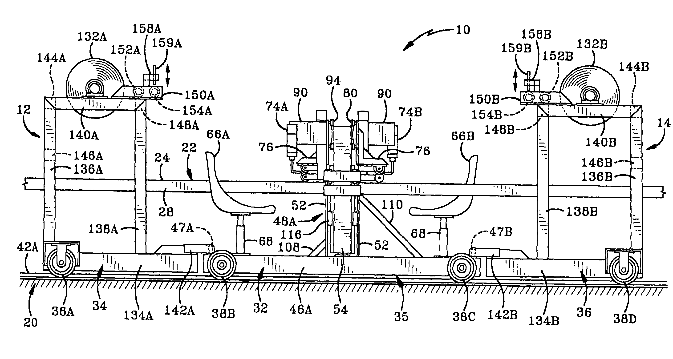
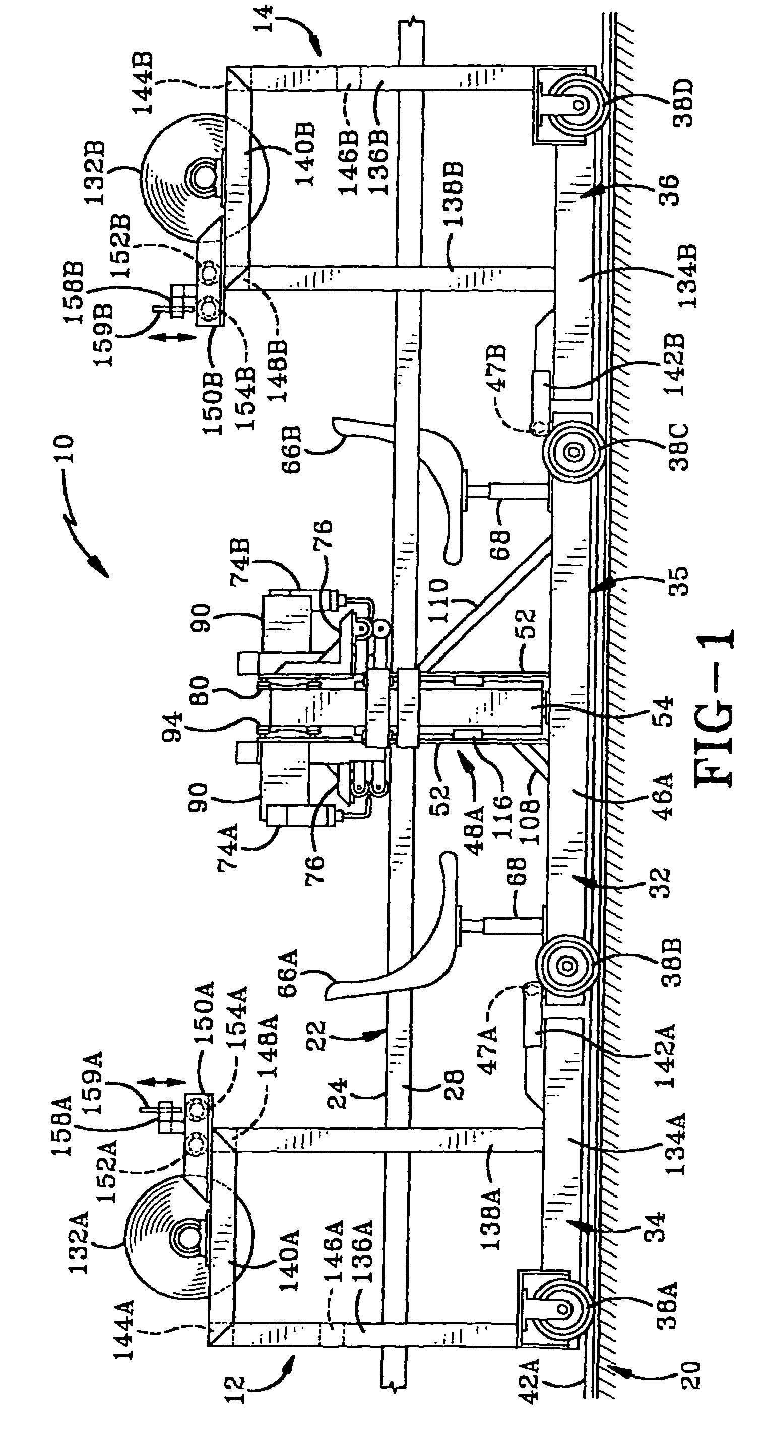
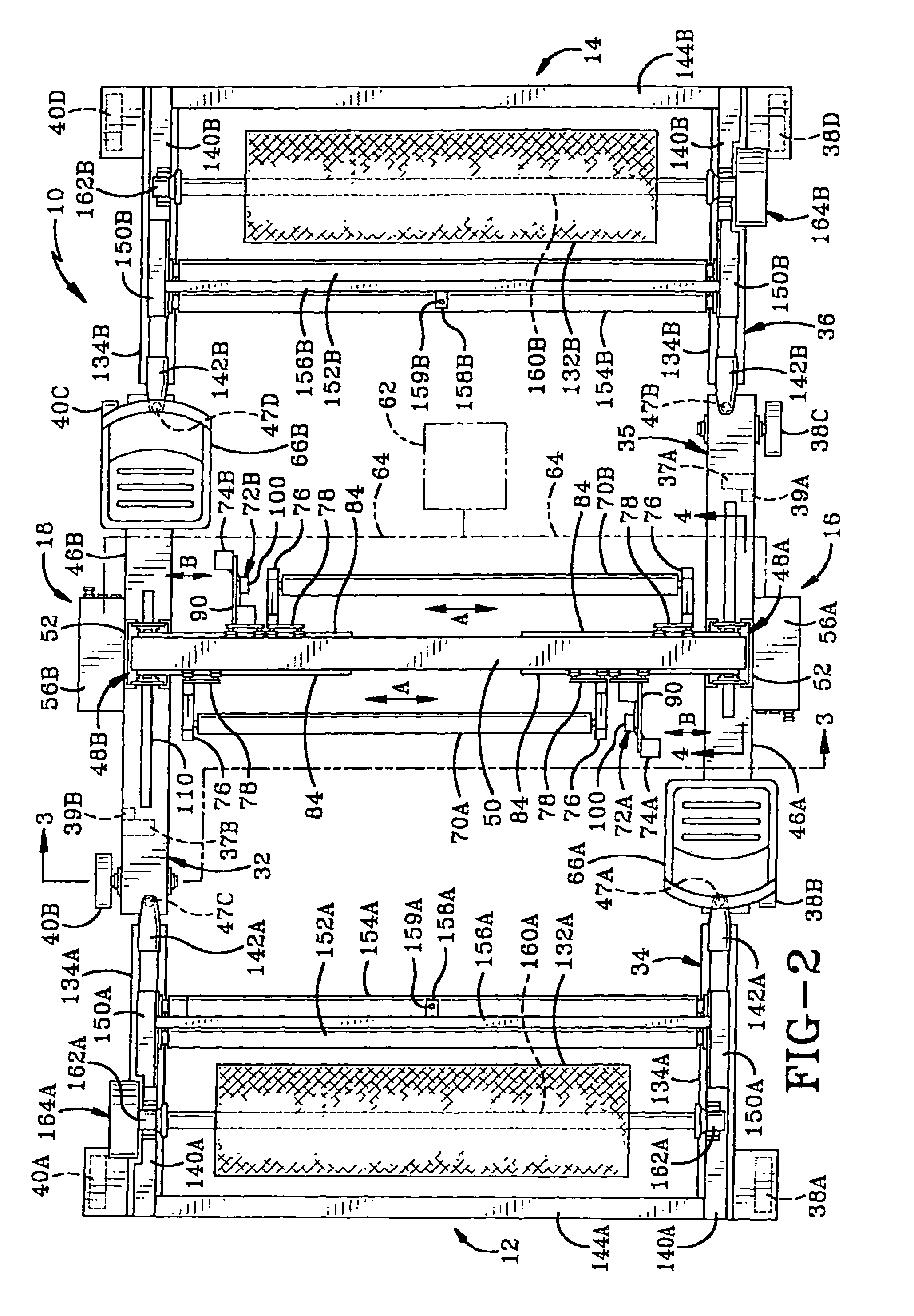
[0033]The bi-directional seaming machine of the present invention is shown generally at 10 in FIGS. 1 and 2. In the exemplary embodiment, machine 10 is shown as a plastic welding machine in which plastic welders are used to form seams between various segments of sheet material. However, machine 10 also represents various other types of seaming machines, such as ultrasonic welding machines, radio frequency (RF) welding machines, adhesive seaming machines, gluing seaming machines and sewing machines. Seaming machine 10 is used to seam together various segments of sheet material to form relatively large sheets of material, such as tarpaulins for covering trailers and the like, tents, playing field covers, construction site covers, fuel storage cells, advertising balloons, pool covers, awnings, pit liners, inflatable buildings and structures, greenhouses, canopies, banners, pond liners, boat shipping covers and various other items.

[0034]As shown in FIGS. 1 and 2, machine 10 has first an...


PUM

PropertyMeasurementUnit
areaaaaaaaaaaa
rotationaaaaaaaaaa
heightaaaaaaaaaa

Abstract

A seaming machine for seaming segments of sheet material to one another to form larger sheets includes a frame defining a sheet-receiving area and a pair of spaced seaming devices on opposed sides of the sheet-receiving area for respectively seaming opposed edges of the segments of sheet material to one another. The frame typically defines a table-receiving space for a table to support the sheet segments. The machine provides for the seaming of multiple sheet segments while the sheet segments remain atop the table or another work surface. Relative back and forth movement between the frame and work surface facilitate the process.

Description

CROSS REFERENCE TO RELATED APPLICATIONS[0001]This application claims priority from U.S. Provisional Application Ser. No. 61 / 133,376 filed Jun. 27, 2008; the disclosure of which is incorporated herein by reference.BACKGROUND OF THE INVENTION[0002]1. Technical Field[0003]The present invention relates generally to seaming machines. More particularly, the invention relates to a seaming machine and method of seaming a number of sheet segments to form a larger sheet of material. Specifically, the invention relates to a bi-directional seaming machine which expedites the process of producing the seams between the sheet segments.[0004]2. Background Information[0005]The seaming together of multiple sheets of material is well known in the art. Typically, a first segment of sheet material is laid on a table or other work surface and a second segment of sheet material is positioned above the first segment with their edges generally aligned so that a seaming device moves along the aligned edges t...

Claims


Application Information

Patent Timeline
Patent Type & Authority Patents(United States)
IPC IPC(8): D05B23/00D05B35/02D05B9/00
CPCB29C65/5042B29C66/1122B29C66/1142B29C66/135B29C66/43B29C66/435B29C66/8362B23P11/00B29C66/112B29C66/81417B29C66/431B29C65/04Y10T156/1712B29C65/10B29C65/20B29C65/62B29C66/84B29K2021/00B29K2021/003B29K2023/06B29K2023/12B29K2027/06B29K2075/00B29K2101/12B29L2007/005B29C65/08Y10T29/49826B29C65/5092B29C65/4835B29C65/48B29C65/4815B29C65/00B29C66/71
Inventor HENRY, BRIAN D.TUNISTRA, RODNEY M.
Owner MILLER WELDMASTER CORP
Why Eureka
Try Eureka