Composite profile provided with a support body made of a light metal material and a profiled strip and a method for producing said profile

a technology of light metal material and supporting body, applied in the direction of workpiece edge portions, power rails, railway tracks, etc., can solve the problems of undulation on the upper surface of the covering profile, conductor rails, disadvantages, etc., and achieve the effect of reducing the height toleran

Active Publication Date: 2011-06-07
CONSTELLIUM SWITZERLAND
View PDF14 Cites 1 Cited by
  • Summary
  • Abstract
  • Description
  • Claims
  • Application Information

AI Technical Summary

Benefits of technology

[0008]The foregoing object is achieved wherein attached to the profile strip or covering profile which more or less rests on the top or upper surface of the carrier profile and is preferably made of special steel, on each of its longitudinal sides, is an anchor or insertion rod which is parallel to the longitudinal axis of the profile strip and which on the other side engages in a lateral insertion slot in the carrier profile; the insertion rod or insertion profile is preferably made of the material of the profile strip and joined to the latter by a weld seam. The insertion rods complement the profile strip on both sides and, owing to the welded connection, form a reliable protection for the inside surface of the live carrier profile.
[0010]With a profile strip of channel-like shape which rests on the rail head of a rail-like carrier profile, it proved advantageous to connect the insertion rod to a side arm formed integrally on a base plate of the profile strip, and on the other side to insert it with at least one rod section projecting from that side arm, in the correspondingly arranged insertion slot in the carrier profile. The weld seam is advantageously to run at the end face of the side arm of that profile strip.
[0025]A requirement is a maximum possible width of the sliding surface with the possibility of brushing from the side and mechanical anchoring which, even when the wear profiles are completely worn down, ensures anchoring of the sliding surfaces of which two then remain. Also, a reduction of the fitted height tolerances compared with known composite profiles is desirable. The possibility of local manufacture worldwide without having to upgrade a large light metal extruder is also desirable.

Problems solved by technology

Conductor rails of which the wear components are attached to the live carrier profile by screws or additional insertion members passing through them laterally, have also proved to be disadvantageous.
Other known manufacturing methods may disadvantageously lead to undulations on the upper surface of the covering profile which originate from stepwise caulking or stamping of the carrier profile.

Method used


Image

  • Composite profile provided with a support body made of a light metal material and a profiled strip and a method for producing said profile
  • Composite profile provided with a support body made of a light metal material and a profiled strip and a method for producing said profile
  • Composite profile provided with a support body made of a light metal material and a profiled strip and a method for producing said profile

Examples


Embodiment Construction

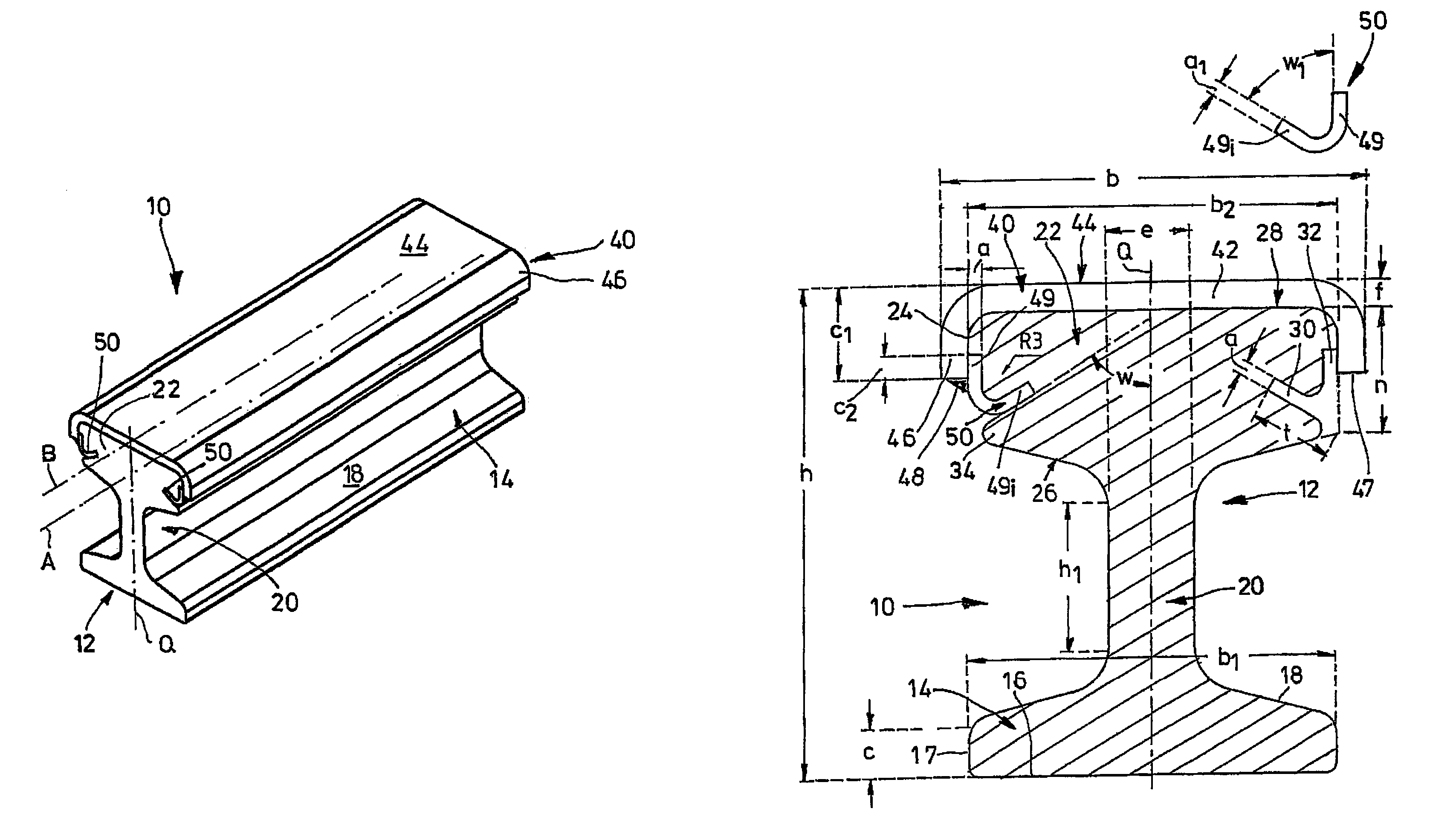
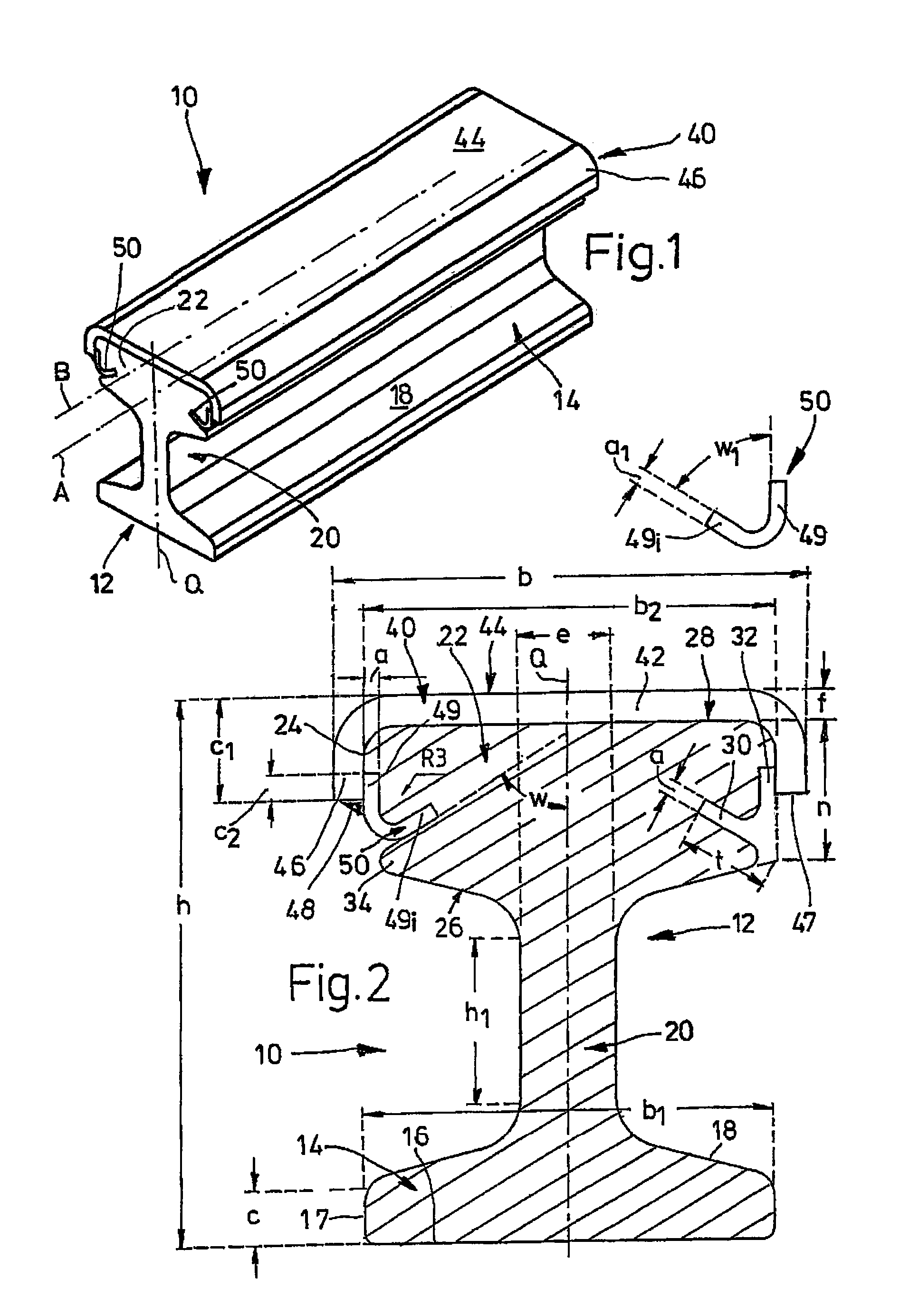
[0041]A composite profile 10 having a height h of 105 mm here and a maximum width b of 92 mm comprises according to FIG. 1 a rail-shaped carrier profile 12 with a rail base 14 and an endless rail head 22 formed integrally on the rail base 14 by means of a rail stem 20. Two longitudinal edges 17 with a height c of 10 mm defining the bottom surface 16 of the rail base 14 run parallel to each other at a distance b1 of 80 mm here.

[0042]From these longitudinal edges 17, the two roof surfaces 18 of the rail base 14 are inclined slightly upwards to the cross-sectional centre axis Q traversing the longitudinal axis A of the composite profile 10, and merge with that rail stem 20 having a height h1 of approximately 30 mm and a thickness e of approximately 18 mm. From the upper end of the rail stem 20 extend the lower surfaces 26 of the rail head 22 which are inclined approximately upwards to the longitudinal edges 24 of this rail head 22, which has a width b2 of 78 mm and of which the outside...


PUM

PropertyMeasurementUnit
apex angleaaaaaaaaaa
angleaaaaaaaaaa
angleaaaaaaaaaa

Abstract

A composite profile comprising a carrier profile made of a light metal material and a profiled strip which is made of a harder material and covers the top surface of the carrier profile. An insertable bar is added to the profiled strip on each longitudinal side in a position parallel to the direction thereof and is inserted into a lateral slot embodied therein. The insertable bar is firmly connected to the profiled strip thereof by a weld seam.

Description

CROSS REFERENCE TO RELATED APPLICATIONS[0001]This application is related to U.S. application Ser. No. 11 / 711,397 filed Feb. 27, 2007 and U.S. application Ser. No. 11 / 708,210 filed Feb. 20, 2007.BACKGROUND OF THE INVENTION[0002]The invention concerns a composite profile having a rail-like support body extruded from light metal material and a profile strip spanning its top surface and made of a harder metal. Also, the invention covers a method for making such a composite profile.[0003]In DE 24 32 541 A1 can be found a method for making conductor rails consisting of a carrier profile and at least one covering which forms at least part of the upper surface of the carrier profile serving as the conductor and consists of a profile strip of a different metal as a covering profile with high abrasion resistance. During an extrusion process, the carrier profile is produced by forcing a bar out through the shaping cross-section of an extrusion die, and at the same time the profile strip passes...

Claims


Application Information

Patent Timeline
Patent Type & Authority Patents(United States)
IPC IPC(8): B60M1/00B21K9/00F16S1/02F16S3/00
CPCB21K9/00B23K33/00B60M1/302E01B5/08Y10T29/49117B23K2201/26B23K2101/26B60M1/32
Inventor WOEMPNER, DIETHELMNETZEL, TIMO
Owner CONSTELLIUM SWITZERLAND
Why Eureka
Try Eureka