Spindle head for machine tool

a machine tool and spindle head technology, applied in the direction of attachment devices, boring/drilling components, manufacturing tools, etc., can solve the problems of not being compatible with a high-output spindle motor and unable to pass a thicker power line, so as to minimize the occurrence of a break, large spatial room, and the effect of large spa

Inactive Publication Date: 2011-05-10
TSUDAKOMA KOGYO KK
View PDF11 Cites 10 Cited by
  • Summary
  • Abstract
  • Description
  • Claims
  • Application Information

AI Technical Summary

Benefits of technology

[0013]According to the present invention, in the above-described machine-tool spindle head (1), the through holes (12) through which a plurality of wires (22) (e.g., a power line for the spindle motor and a signal line for the sensor) extending from the spindle unit (4) are laid are provided in the plurality of support shafts (9, 30, 31), and the plurality of wires (22) are divided into two wire groups, and the wire groups are separately laid in the pair of support shafts (9, 30, 31). Therefore, there is larger spatial room in the wiring paths of the support shafts than when the plurality of wires (22) extending from the spindle unit (4) are passed and laid in one of the support shafts, and this can minimize the occurrence of a break in the wires laid in the support shafts due to twisting and rubbing with the rotation of the support shafts. Moreover, since there is large spatial room in the routing path, a thicker power line can be inserted, and a higher-output spindle motor can be adopted in the spindle head.
[0014]Further, the power line (22a) for supplying driving current to the spindle motor (5) and the signal line (22b) for outputting the signal from the sensor provided in the spindle unit, which are included in the plurality of wires (22), are separately laid in the different wire groups. With this, it is possible to prevent noise produced from the power line from adversely affecting the signal line and to thereby obtain an accurate detection value.
[0015]In addition, the following advantage can be expected by making the structures in the fork arms (7) line-symmetrical with respect to the rotation axis (C-axis) of the spindle (3) in the spindle unit (4).
[0016]That is, the driving motor generates heat with driving of the support head, and the heat sometimes causes thermal displacement of the structure including the components around the driving motor. In this case, if there is a difference between the structures in the fork arms including the support shafts for supporting the spindle unit on the right and left sides in the direction of the turn axis (A-axis), the structural state change due to the thermal displacement is different between the fork arms. With this, the spindle unit supported on both sides by the support shafts in the fork arms sometimes tilts, the axis of the spindle deviates to the right or left, and working accuracy decreases. In contrast, when the structures in the fork arms, especially the structures including the main components are symmetrical, the structural state change due to the thermal displacement is the same between the fork arms, and it is therefore possible to prevent the above-described deviation of the axis of the spindle.

Problems solved by technology

When a plurality of cables and pipes are passed through the support shaft, there is no spatial room in the through hole of the support shaft, and a break may be caused by twisting and rubbing of the cables with the rotation of the support shaft.
Further, since there is no spatial room, it may be impossible to pass a thicker power line and to be compatible with a high-output spindle motor.

Method used


Image

  • Spindle head for machine tool
  • Spindle head for machine tool
  • Spindle head for machine tool

Examples


Embodiment Construction

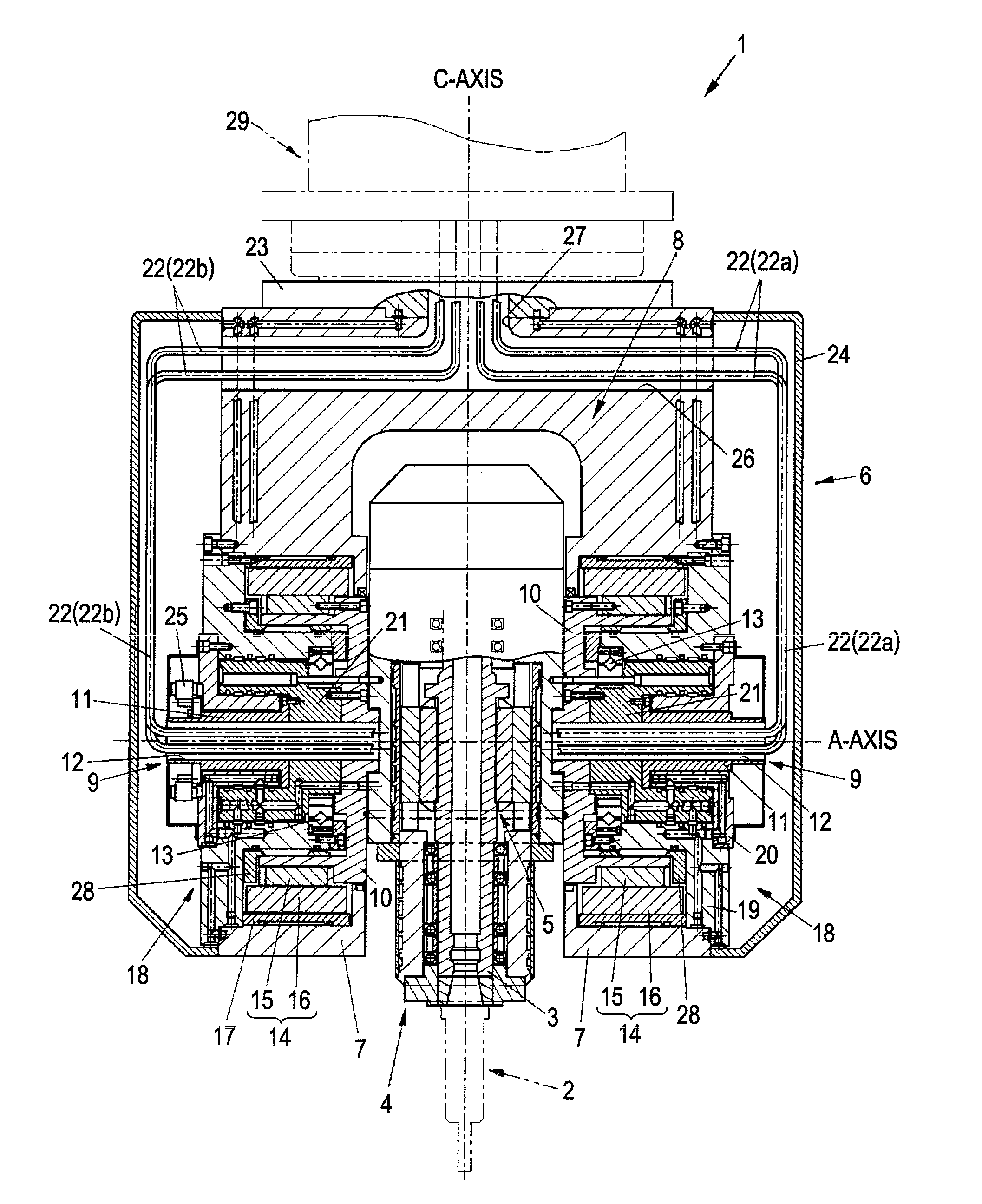
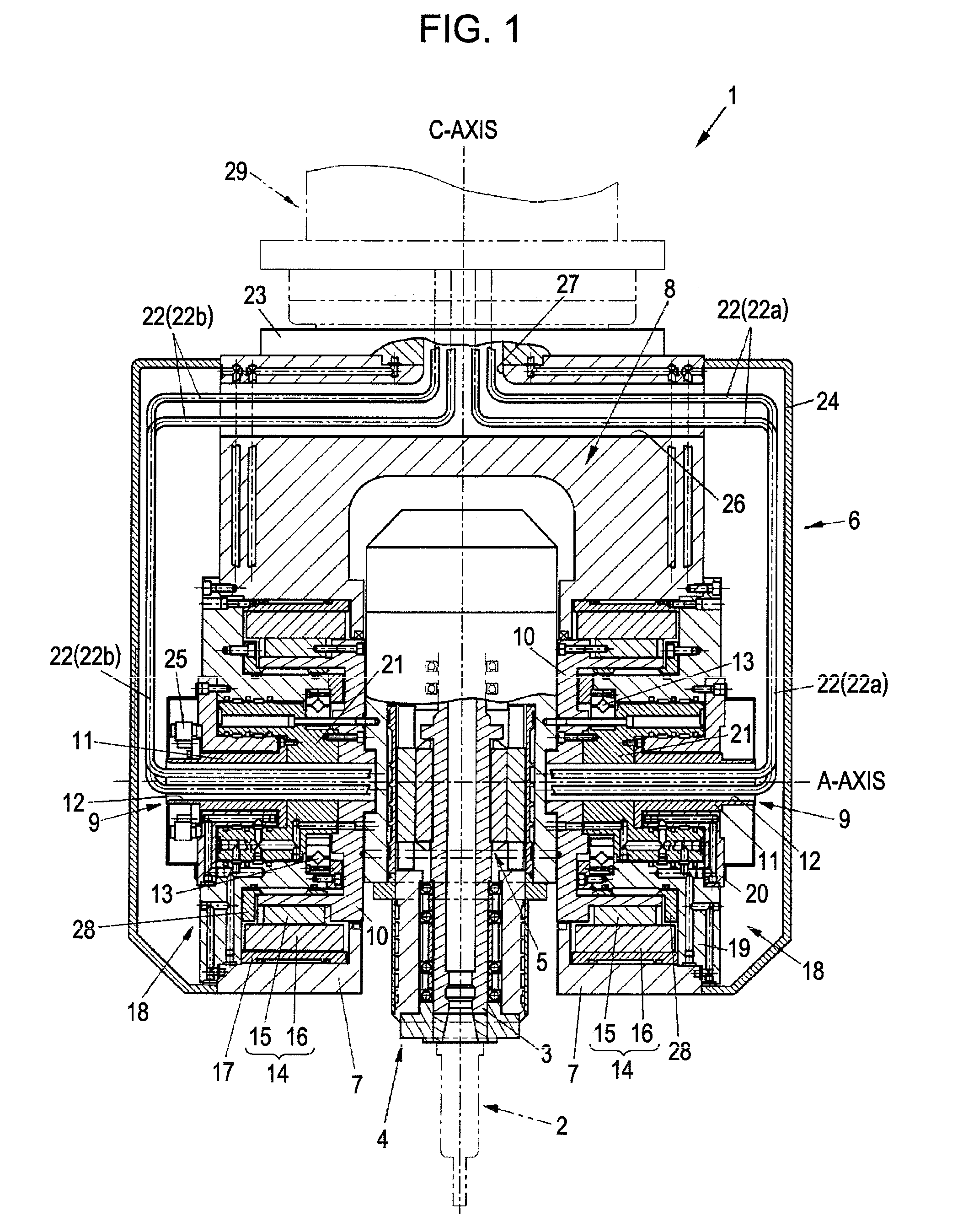
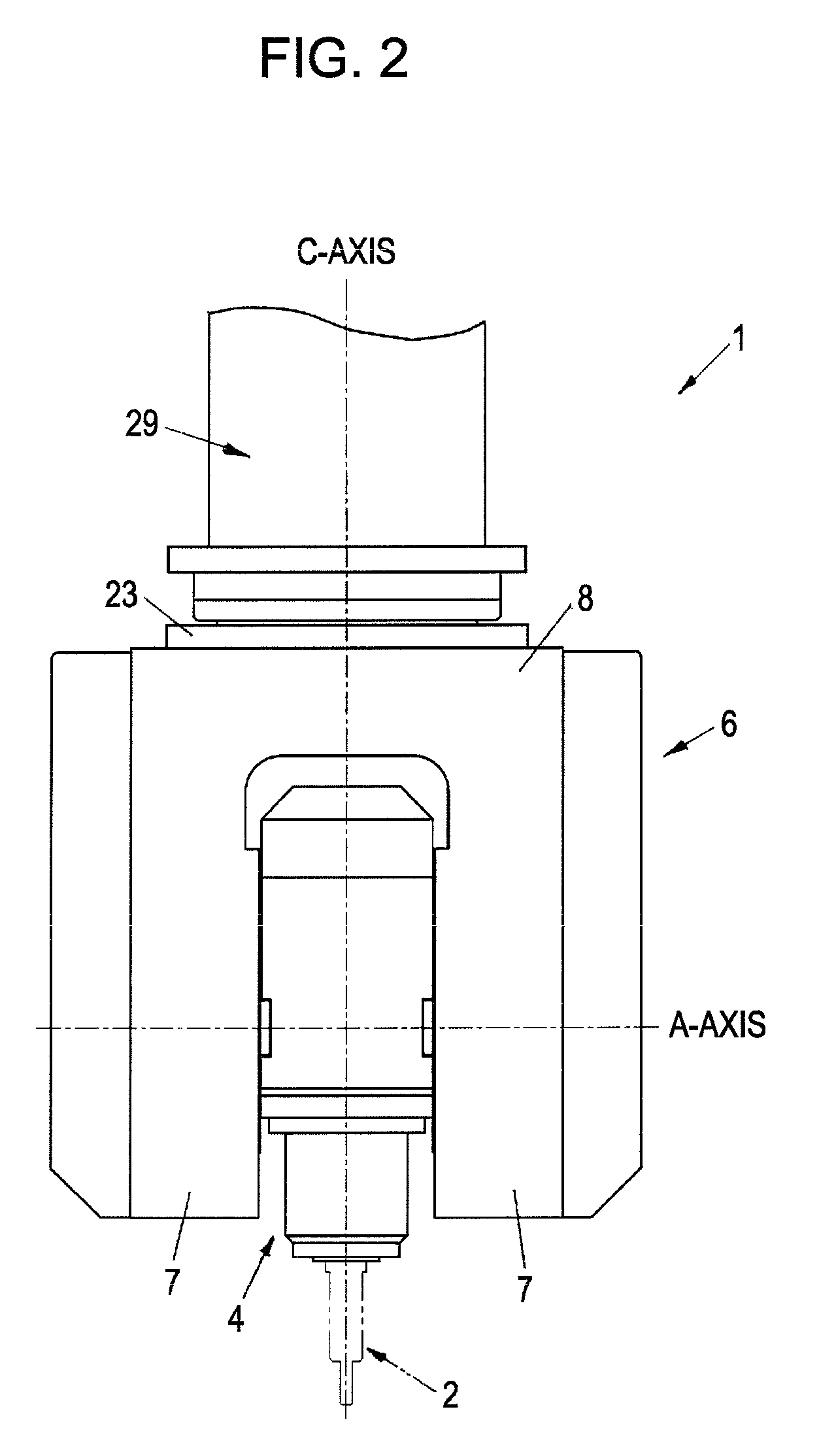
[0069]A spindle head to which the present invention is directed is used in a machine tool such as a vertical machining center (multitask machine). A description will be given below of an embodiment in which the present invention is applied to a vertical machining center.

[0070]FIGS. 1 and 2 illustrate a machine-tool spindle head 1 according to the present invention. The machine-tool spindle head 1 refers to a device that is used in a vertical machining center or the like and that supports and turns a spindle unit 4 to which a tool 2 is attached. Here, when the machine-tool spindle head 1 is mounted in a vertical machining center or the like, it entirely moves in the X-, Y-, and Z-directions of the machine tool, and the spindle unit 4 supported by the machine-tool spindle head 1 rotates on an axis (A-axis) parallel to the X-Y plane and on an axis (C-axis) parallel to the Z-axis.

[0071]The machine-tool spindle head 1 includes a spindle 3 having an end to which a tool 2 is attached, the ...


PUM

PropertyMeasurementUnit
speedsaaaaaaaaaa
speedaaaaaaaaaa
rotation axisaaaaaaaaaa

Abstract

A support shaft of a spindle unit having a through hole in which wires are laid has a structure that can obtain much spatial room so as to prevent a break in cables and to be compatible with a high-output spindle motor. A machine-tool spindle head 1 includes a support head 6 that drives a spindle unit 4 for indexing around a turn axis (A-axis) of the spindle unit 4 by rotatably supporting a pair of support shafts 9 coupled to the spindle unit 4 on the A-axis by a pair of fork arms 7 and bearings 13. The pair of support shafts 9 have through holes 12 in which a plurality of wires 22 extending from the spindle unit 4 are laid, the plurality of wires 22 are divided into two wire groups, and the wire groups are separately laid in the pair of support shafts 9.

Description

TECHNICAL FIELD[0001]The present invention relates to a spindle head for a machine tool, and more particularly relates to a structure for supplying electric power and fluid to a spindle unit.BACKGROUND ART[0002]Patent Document 1 discloses a spindle head including a fork-shaped driving portion (A-axis driving portion) that supports a spindle unit for rotating a spindle, to which a tool is attached, and that turns the spindle unit in a machine tool such as a so-called machining center.[0003]The spindle unit rotates the spindle, which is rotatably supported in a housing of the spindle unit, by an internal spindle motor (also referred to as a built-in motor). A power line for supplying driving current is connected to the spindle motor, and this power line is led out from the housing of the spindle unit and is laid towards a power supply circuit in the machine tool.[0004]In general, the power line is laid through the housing of the support head for supporting the spindle unit so as not t...

Claims


Application Information

Patent Timeline
Patent Type & Authority Patents(United States)
IPC IPC(8): B23C1/12
CPCB23Q1/0009B23Q1/5406Y10T409/308512Y10T409/309352Y10T408/93B23Q2220/006
Inventor TATSUDA, YOSHINORINISHITA, YOICHI
Owner TSUDAKOMA KOGYO KK
Why Eureka
Try Eureka