
Semi-autonomous excavation control system

a control system and semi-autonomous technology, applied in the field of excavation control system, can solve the problems of limited benefit, many manual tasks, and difficulty in executing productive and efficient control of excavation machines,

Active Publication Date: 2011-05-03
CATERPILLAR INC
View PDF29 Cites 30 Cited by
  • Summary
  • Abstract
  • Description
  • Claims
  • Application Information

AI Technical Summary

Benefits of technology

[0007]One aspect of the present disclosure is directed to an excavation control system. The excavation control system may include a tool, at least one operator input device configured to provide manual control over movement of the tool, and a controller in communication with the at least one operator input device. The controller may be configured to receive an input related to an operator desired tool location, and determine that an operator is manually controlling movement of the tool toward the operator desired tool location. The controller may be further configured to automatically assume control over movement of the tool toward the operator desired tool location based on the determination.
[0008]Another aspect of the present disclosure is directed to a method of automatically moving a tool during an excavation cycle. The method may include receiving an input related to an operator desired tool location, and determining that an operator is manually controlling movement of the tool toward the operator desired tool location. The method may further include automatically assuming control over movement of the tool toward the operator desired tool location based on the determination, and relinquishing automatic control over movement of the tool to the operator after the tool has reached the operator desired tool location.

Problems solved by technology

Control of an excavation machine can be a difficult task to perform productively and efficiently, without causing operator fatigue.
Although the semi-automatic hydraulic excavator of the '043 patent may simplify manual control thereof, the benefit may be limited.
That is, the operator may still be required to complete many tasks manually (e.g., boom lift and boom swing), even during the autonomous portion of the excavation cycle.

Method used


Image

  • Semi-autonomous excavation control system
  • Semi-autonomous excavation control system
  • Semi-autonomous excavation control system

Examples


Embodiment Construction

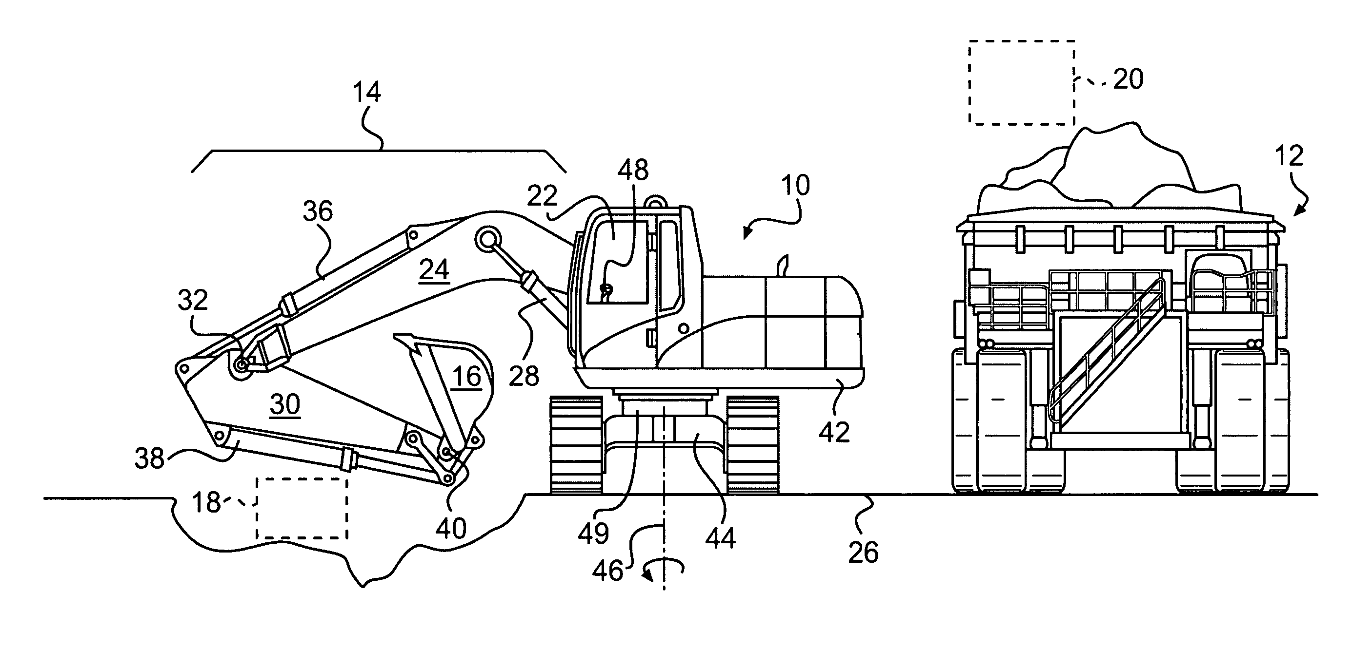
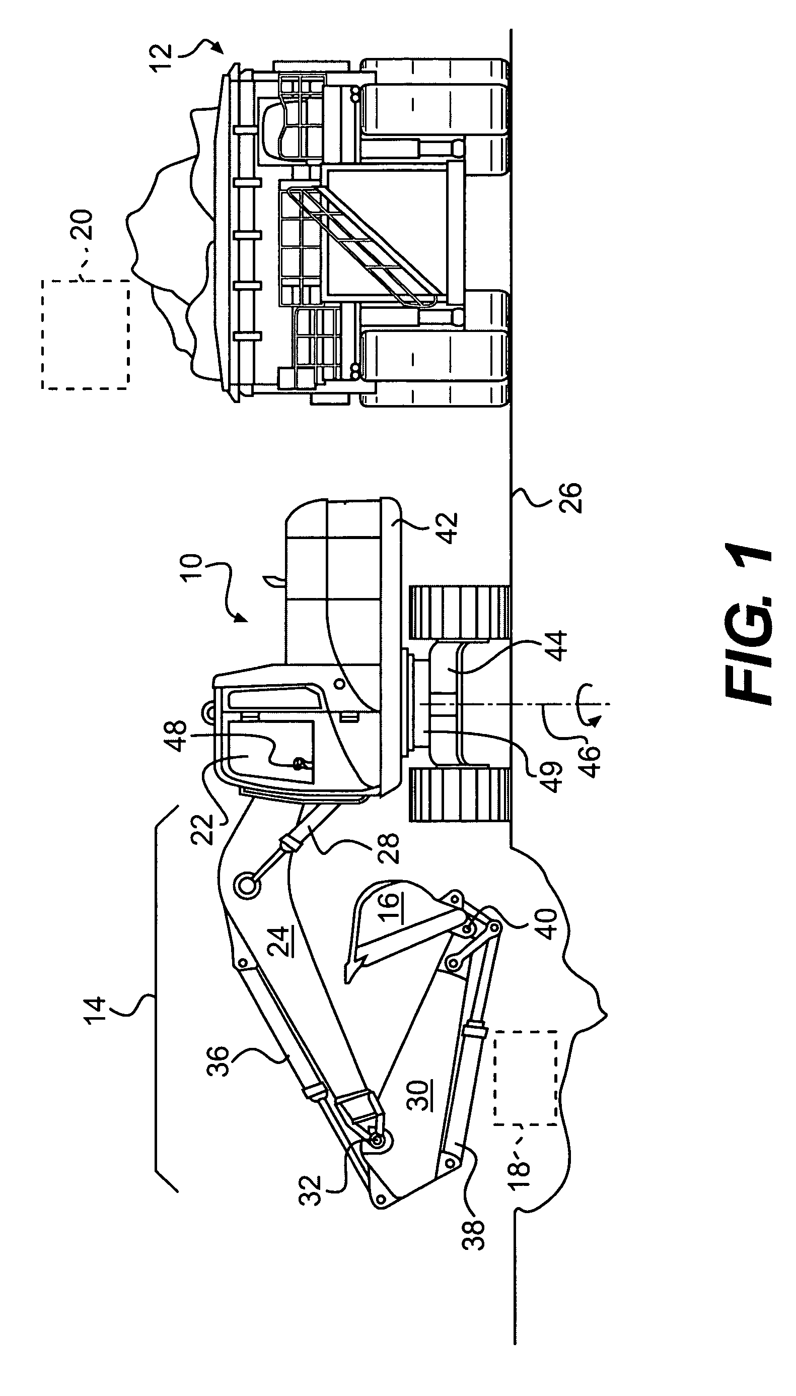
[0011]FIG. 1 illustrates an exemplary machine 10 having multiple systems and components that cooperate to excavate and load earthen material onto a nearby haul vehicle 12. In one example, machine 10 may embody a hydraulic excavator. It is contemplated, however, that machine 10 may embody another type of excavation machine such as a backhoe, a front shovel, a wheel loader, or another similar machine, if desired. Machine 10 may include, among other things, an implement system 14 configured to move a work tool 16 between a dig location 18 and a dump location 20 over haul vehicle 12, and an operator station 22 for manual control of implement system 14.

[0012]Implement system 14 may include a linkage structure acted on by fluid actuators to move work tool 16. Specifically, implement system 14 may include a boom member 24 vertically pivotal relative to a work surface 26 by a pair of adjacent, double-acting, hydraulic cylinders 28 (only one shown in FIG. 1). Implement system 14 may also inc...


PUM


Abstract

An excavation control system for a machine is disclosed. The excavation control system may have a tool, at least one operator input device configured to provide manual control over movement of the tool, and a controller in communication with the at least one operator input device. The controller may be configured to receive an input related to an operator desired tool location, and determine that an operator is manually controlling movement of the tool toward the operator desired tool location. The controller may be further configured to automatically assume control over movement of the tool toward the operator desired tool location based on the determination.

Description

TECHNICAL FIELD[0001]The present disclosure relates generally to an excavation control system, and more particularly, to a semi-autonomous excavation control system.BACKGROUND[0002]Control of an excavation machine can be a difficult task to perform productively and efficiently, without causing operator fatigue. Such control can require years of experience and a high level of skill that not all operators posses. In order to ensure optimum performance of an excavation machine, even with inexperienced or low-skill operators, auto-dig systems are commonly utilized. Auto-dig systems automate many of the repetitive operations normally performed by a human operator.[0003]A typical cycle for an excavation machine includes a dig segment, a swing-to-truck segment, a dump segment, and a swing-to-trench segment. Some of these segments are best performed by an operator, while others can be performed autonomously to reduce the fatigue of the operator and / or to reduce the skill or experience level...

Claims


Application Information

Patent Timeline
Patent Type & Authority Patents(United States)
IPC IPC(8): G05D1/02
CPCE02F3/437E02F3/434
Inventor MINTAH, BRIANPRICE, ROBERT J.KING, KEVIN D.
Owner CATERPILLAR INC
Learn More