Coaxial connector with a coupling body with grip fingers engaging a wedge of a stabilizing body

Active Publication Date: 2011-04-19
COMMSCOPE TECH LLC
View PDF18 Cites 130 Cited by
  • Summary
  • Abstract
  • Description
  • Claims
  • Application Information

AI Technical Summary

Benefits of technology

[0028]Because the grip fingers 15 are integral with the monolithic coupling body 3, manufacture and assembly are simplified as there are no additional separate components to verify / supply to the assembly area and any additional assembly steps required by such discrete elements are eliminated. Further, the coupling body assembly 1 configuration may be streamlined and materials savings realized as there is no need for additional coupling and / or retaining structures to receive, align and / or retain a separate grip finger element.
[0032]The stabilizing contact may be enhanced with respect to a longitudinal axis direction to also improve a coaxial connector to coaxial cable interconnection mechanical tear off strength, by applying a plurality of inward projecting protrusion(s) 27 to the inner diameter of the grip fingers 15. Further, the inward projecting protrusion(s) 27 may improve a coaxial connector to coaxial cable anti-rotation characteristic of the stabilizing contact and thereby of the coaxial connector to coaxial cable interconnection.
[0035]One skilled in the art will appreciate the manufacturing, installation and interconnection stabilizing benefits of the invention. Significantly, the stabilizing contact with the coaxial cable is obtained with minimal additional cost via the modifications to the cable end 7 of the coupling body 3 to add the grip fingers 15 and the addition of only one additional element, the stabilizing body.

Problems solved by technology

Rotation of the coaxial cable and coaxial connector with respect to each other may damage the connector, cable and / or the integrity of the cable / connector inter-connection.
Further, once installed, twisting, bending and / or vibrations applied to the interconnection over time may degrade the connector to cable interconnection and / or introduce PIM.
Therefore, any stabilizing effect obtained from the environmental seal is limited.

Method used


Image

  • Coaxial connector with a coupling body with grip fingers engaging a wedge of a stabilizing body
  • Coaxial connector with a coupling body with grip fingers engaging a wedge of a stabilizing body
  • Coaxial connector with a coupling body with grip fingers engaging a wedge of a stabilizing body

Examples


Embodiment Construction

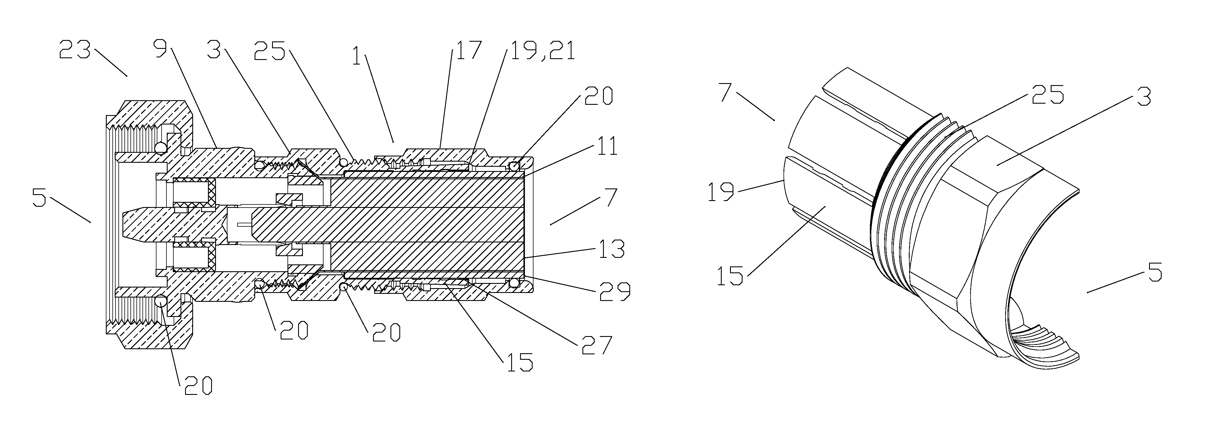
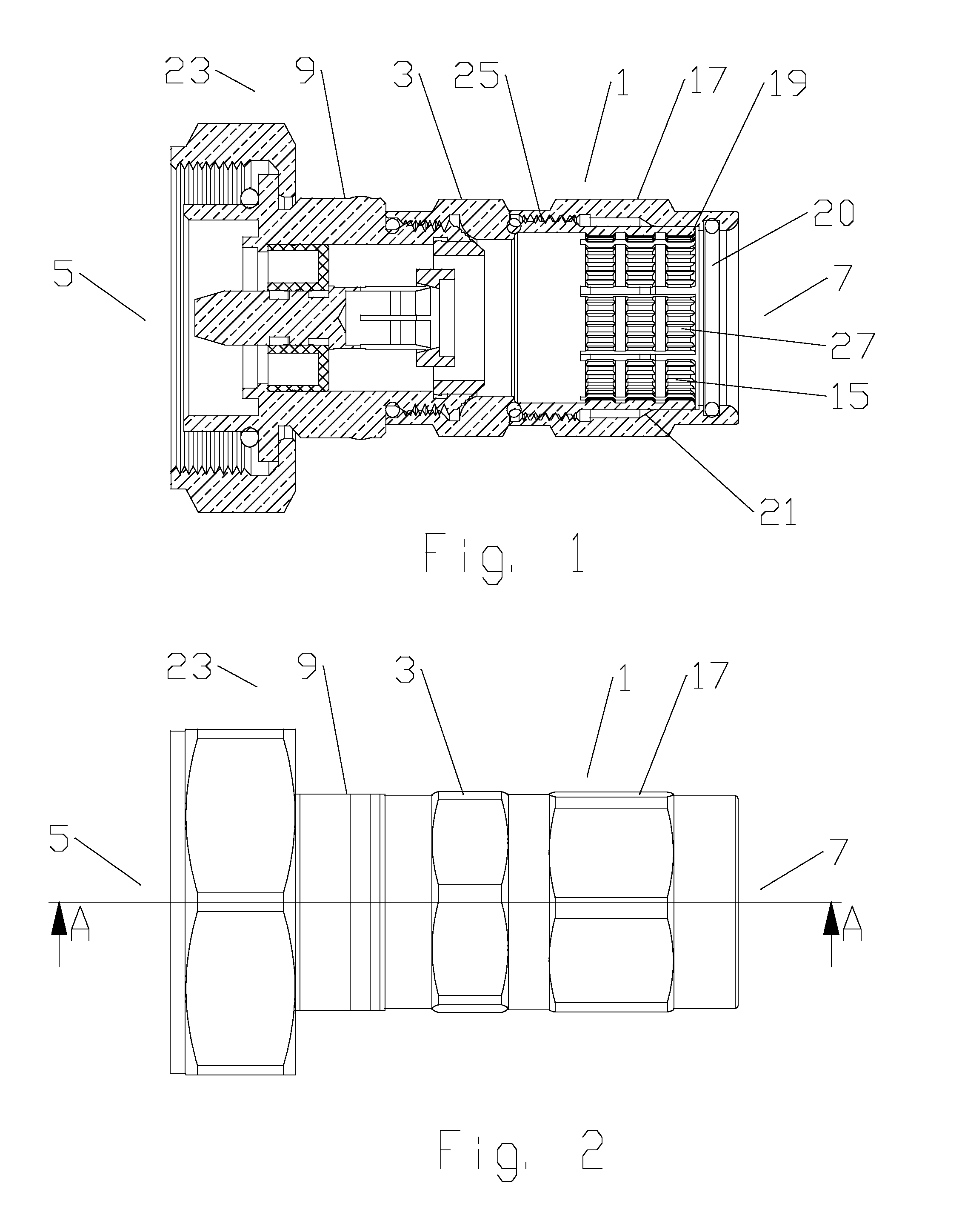
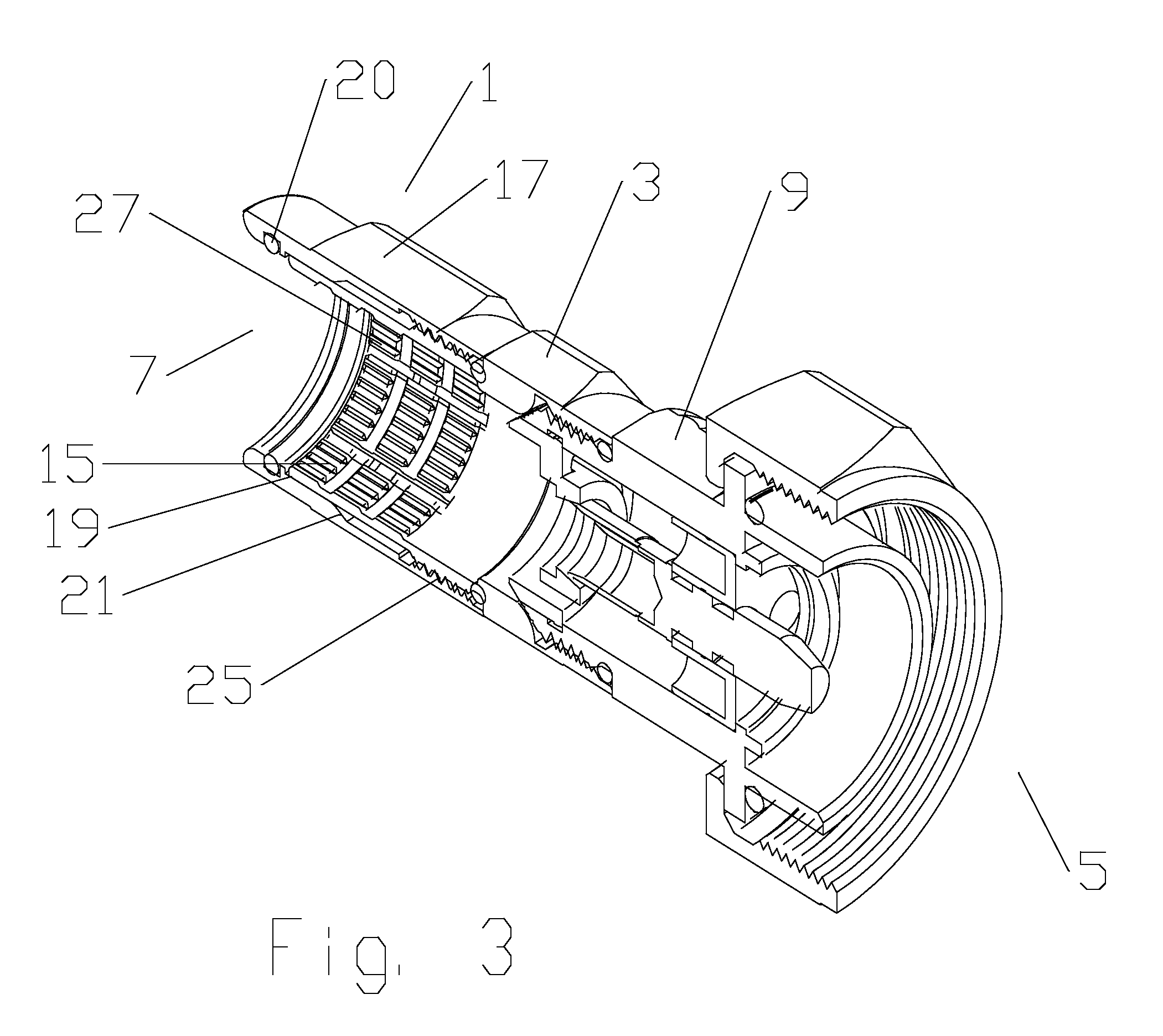
[0022]The inventor has recognized that movement and / or skewing of alignment between the connector and coaxial cable may generate unacceptable levels of PIM and / or otherwise compromise the electromechanical interconnection, for example as contact surfaces shift relative to one another and / or less than uniform circumferential contact occurs between the electrical contacting elements of the connector and the inner and / or outer conductors.

[0023]An exemplary embodiment of a coupling body assembly 1 with a connector to cable interconnection stabilizing functionality is demonstrated in FIGS. 1-12. As best shown in FIGS. 1-3, the coupling body assembly 1 includes a coupling body 3 dimensioned to couple at a connector end 5 of the coupling body 3 with a cable end 7 of a coaxial connector body 9.

[0024]One skilled in the art will appreciate that connector end 5 and cable end 7 are applied herein as identifiers for respective ends of both the overall assembly and also of discrete elements of th...


PUM


Abstract

A stabilizing coupling body assembly for a connector is provided with a monolithic coupling body dimensioned to couple with a cable end of a connector body of the connector. A plurality of grip fingers extends from a cable end of the coupling body, the grip fingers dimensioned for insertion within a bore of a stabilizing body. The stabilizing body is coupled to a cable end of the coupling body. A distal end of the grip fingers is proximate an annular wedge surface of the bore of the stabilizing body. The wedge surface is provided with a taper between a maximum diameter proximate a connector end and a minimum diameter proximate a cable end. The grip fingers are driven radially inward as the stabilizing body is advanced axially towards the coupling body. Methods of manufacture include forming elements of the coupling body assembly via injection molding and / or machining.

Description

FIELD OF THE INVENTION[0001]This invention relates to electrical cable connectors. More particularly, the invention relates to a connector stabilizing coupling body assembly for improving connector to cable retention and passive intermodulation distortion (PIM) electrical performance.DESCRIPTION OF RELATED ART[0002]Coaxial cable connectors are used, for example, in communication systems requiring a high level of precision and reliability.[0003]To create a secure mechanical and optimized electrical interconnection between the cable and the connector, it is desirable to have generally uniform, circumferential contact between a leading edge of the coaxial cable outer conductor and the connector body. A flared end of the outer conductor may be clamped against an annular wedge surface of the connector body, via a coupling body. Representative of this technology is commonly owned U.S. Pat. No. 5,795,188 issued Aug. 18, 1998 to Harwath.[0004]Alternative forms of connector to cable end elec...

Claims


Application Information

Patent Timeline
IPC IPC(8): H01R9/05
CPCH01R9/0521H01R24/564H01R2103/00
Inventor WLOS, JAMES
Owner COMMSCOPE TECH LLC
Why Eureka
Try Eureka