
Method and device for supporting a structure

a technology of supporting pedestals and structures, applied in the field of supporting pedestals, can solve the problems of threads not being disengaged to the extent that the two members are not sufficiently rigidly connected, and the range of heights of most pedestals is relatively narrow

Active Publication Date: 2011-04-12
UNITED CONSTR PROD LLC
View PDF16 Cites 42 Cited by
  • Summary
  • Abstract
  • Description
  • Claims
  • Application Information

AI Technical Summary

Benefits of technology

"The patent describes a support pedestal for elevating objects above a surface with adjustable height. The support pedestal has a base member and a support member with a height adjusting member that can be rotated to adjust the height. The support member has a cylindrical wall with support threads that can be engaged with the base member to adjust the height. The support member can also have a support surface for placing the object on. The height adjusting member includes cylindrical threaded engagement portions that can be rotated to adjust the height. The support pedestal can be easily adjusted to the minimum and maximum heights, and the height can be maintained without any gaps. The support pedestal can be used to elevate objects above a surface, and the method includes steps to position the base member and engage the support member with the object."

Problems solved by technology

One problem is that many projects using support pedestals require the use of pedestals of varying heights to accommodate variations in the fixed surface upon which the pedestals are placed, or to create architectural features in the building surface.
However, most pedestals have a relatively narrow range of heights that are obtainable.
Extensions such as that disclosed in U.S. Pat. No. 5,588,264 can be used to increase the height of the pedestal, however such extensions leave a gap in the obtainable pedestal height, which can again require a builder to acquire many different sized pedestals.
Further, another problem that is encountered is that each threaded pedestal member must be rotatably engaged with its mating member to a depth that is sufficient to maintain the structural integrity of the pedestal.
That is, when increasing the height of the pedestal by rotating to pedestal members in relation to each other, the threads cannot be disengaged to the extent that the two members are not sufficiently rigidly connected to maintain the desired pedestal strength.

Method used


Image

  • Method and device for supporting a structure
  • Method and device for supporting a structure
  • Method and device for supporting a structure

Examples


Embodiment Construction

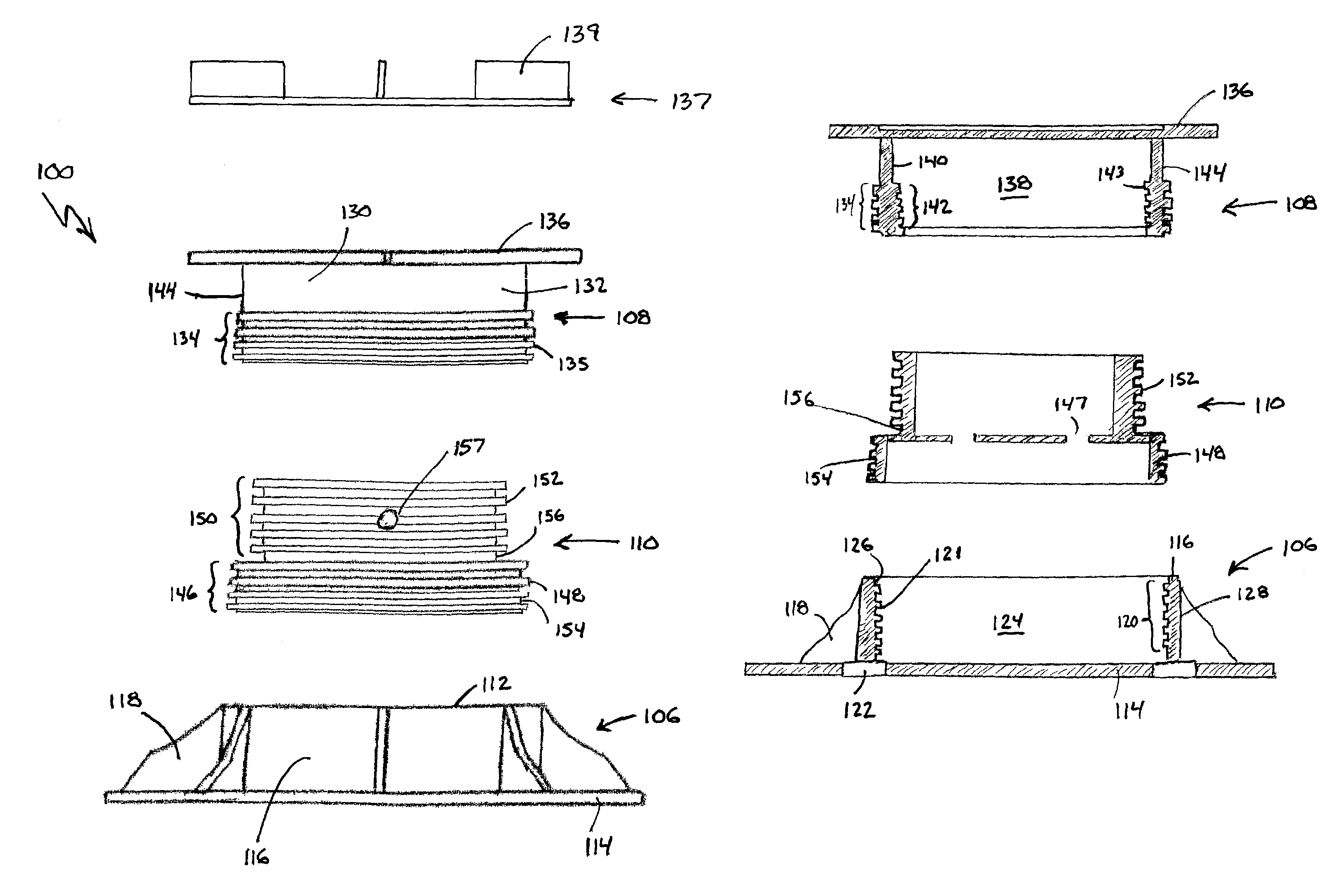
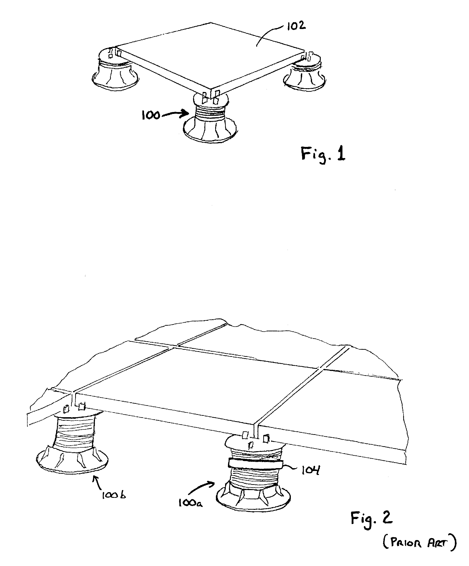
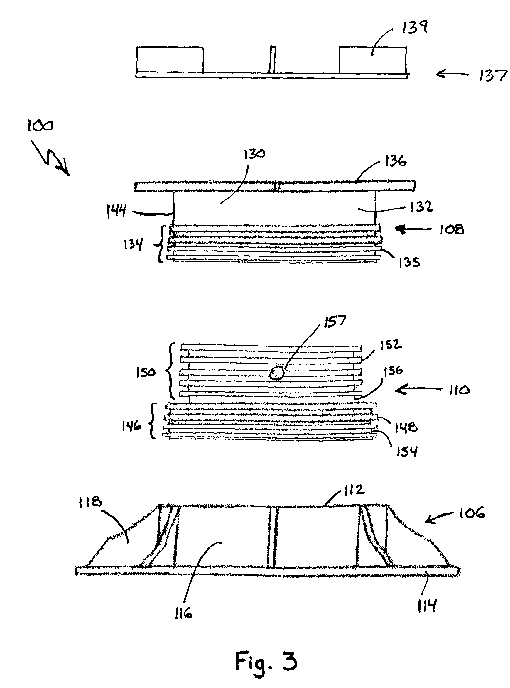
[0029]FIG. 1 illustrates a plurality of support pedestals supporting a concrete paver 102. As is illustrated in FIG. 1, the support pedestals 100 are placed on a fixed surface and support a plurality of pavers 102 above the fixed surface. Although illustrated as supporting a concrete paver 102, it will be appreciated that support pedestals can be utilized to support a wide variety of objects above a wide variety of fixed surfaces. For example, the support pedestals can be placed on fixed surfaces such as rooftops, on-grade (e.g., natural ground), over concrete slabs including cracked concrete slabs, and can be placed within water features. The support pedestals can be utilized to support a variety of objects including, but not limited to, wood tiles, natural stone, concrete pavers, metal or fiberglass grating, composites, or wood planking over traditional wood stringers.

[0030]The object being supported must often be supported over a fixed surface having an uneven grade or slope. To ...


PUM


Abstract

A method and device for supporting a structure above a fixed surface. The device can include a support pedestal whose height is adjustable through a range of heights without a substantial gap in the obtainable heights.

Description

BACKGROUND OF THE INVENTION[0001]1. Field of the Invention[0002]This invention relates to the field of support members. In particular, the present invention relates to support pedestals that are particularly adapted for supporting a structure, such as a walking surface, above a fixed surface.[0003]2. Description of Related Art[0004]One method for supporting building surfaces, such as decks or terraces, is to support the members making up the building surface, such as pavers, panels or timber, with support pedestals. For example, in outdoor applications, the building surface may be elevated above a fixed surface by the pedestals to promote drainage, provide a level structural surface for walking, and / or prevent deterioration of or damage to the surface members.[0005]One example of such a support pedestal is disclosed in U.S. Pat. No. 5,588,264 by Buzon, which incorporated herein by reference in its entirety. The pedestal disclosed by Buzon can be used in outdoor or indoor environment...

Claims


Application Information

Patent Timeline
Patent Type & Authority Patents(United States)
IPC IPC(8): E04B9/00
CPCB23Q1/0054E04D11/007E04F15/0247F16M7/00E04F15/02183Y10T403/56E04F2015/02127
Inventor KNIGHT, III, STEPHEN J.KUGLER, WILLIAM E.
Owner UNITED CONSTR PROD LLC
Learn More