Display device
a liquid crystal display and display panel technology, applied in non-linear optics, instruments, optics, etc., can solve the problems that neither the liquid crystal display panel nor the back light needs to be flexible, and achieve excellent legibility, high reliability, and the effect of avoiding the problem of reliability
- Summary
- Abstract
- Description
- Claims
- Application Information
AI Technical Summary
Benefits of technology
Problems solved by technology
Method used
Image
Examples
embodiment 1
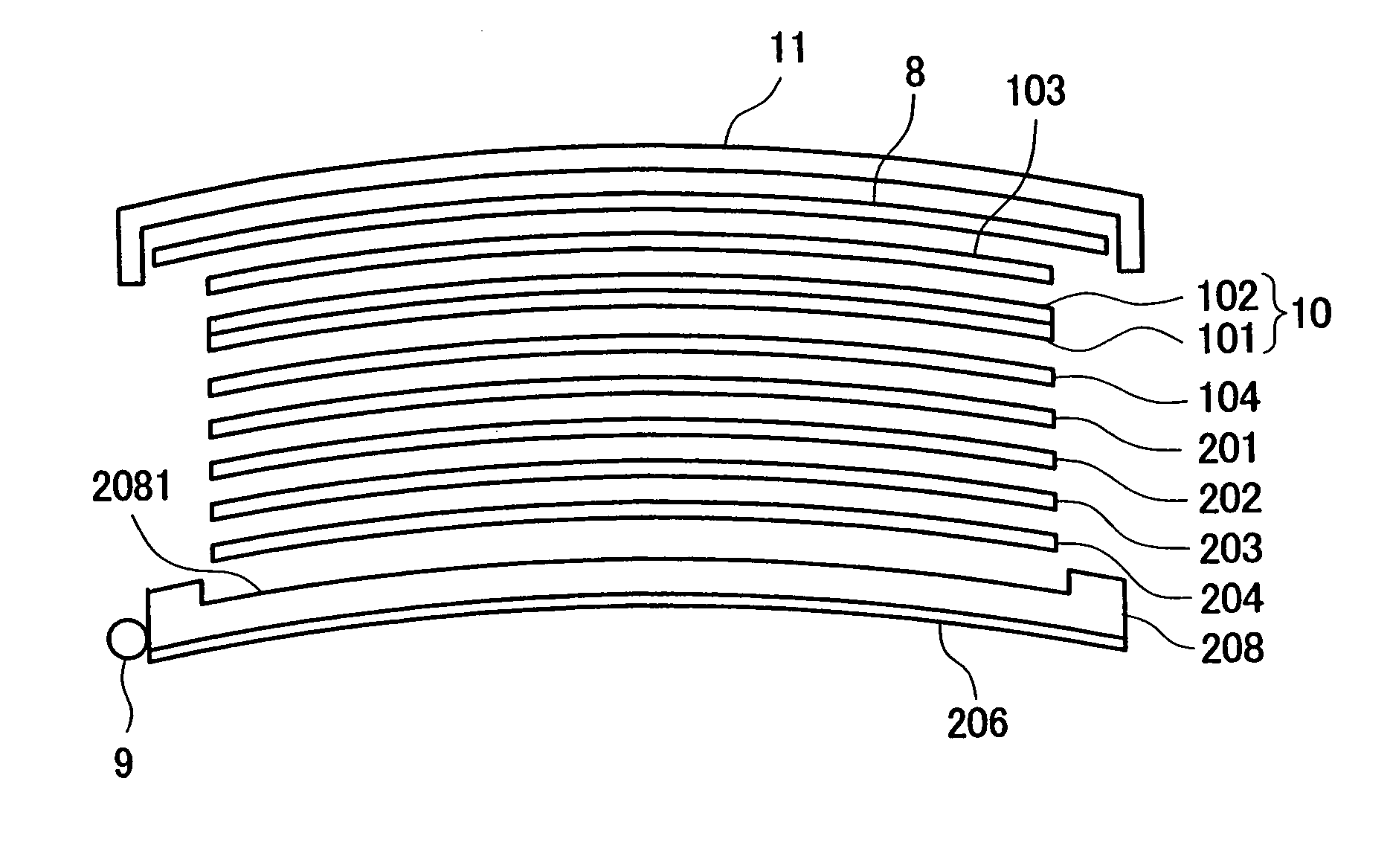
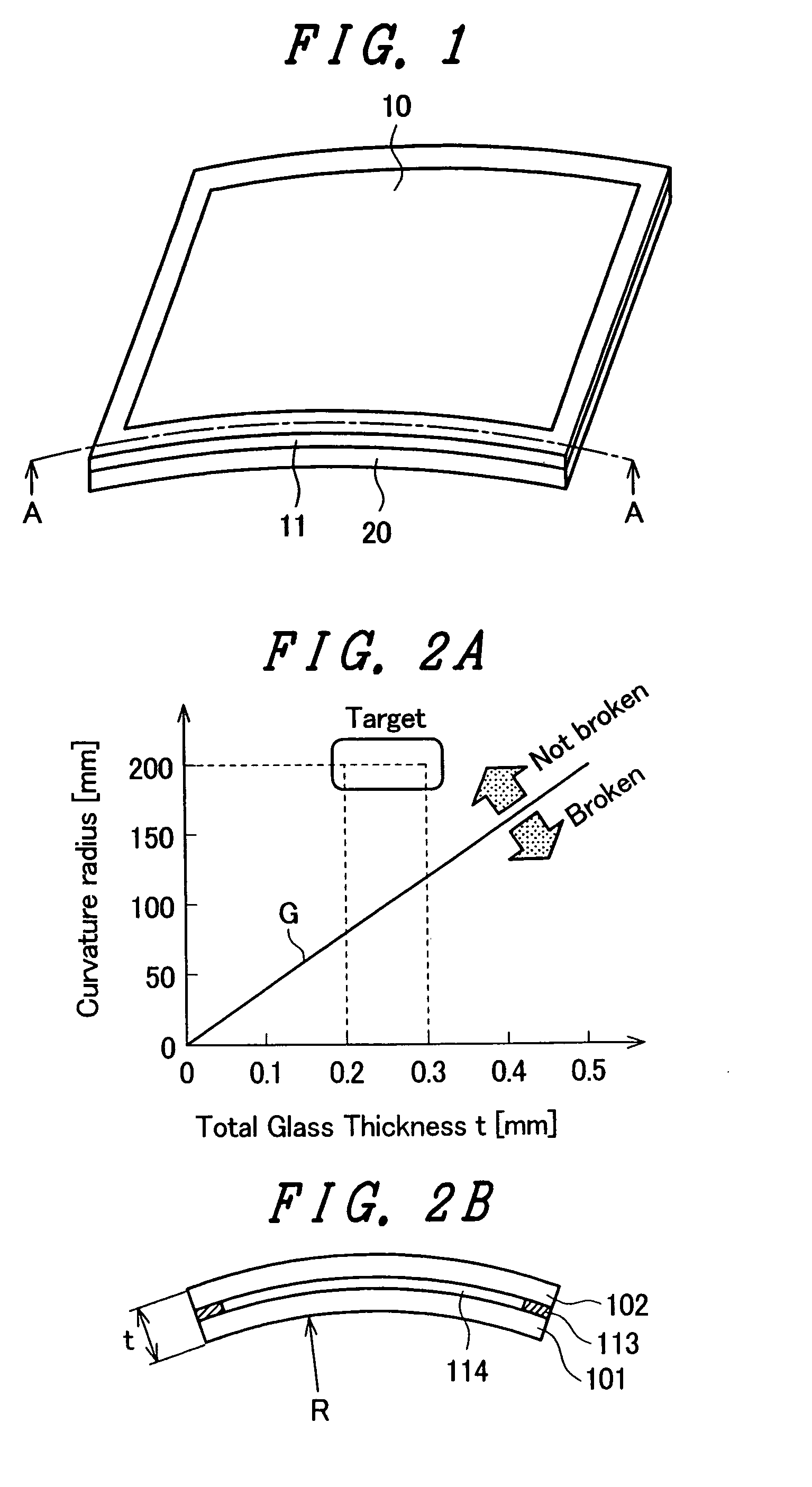
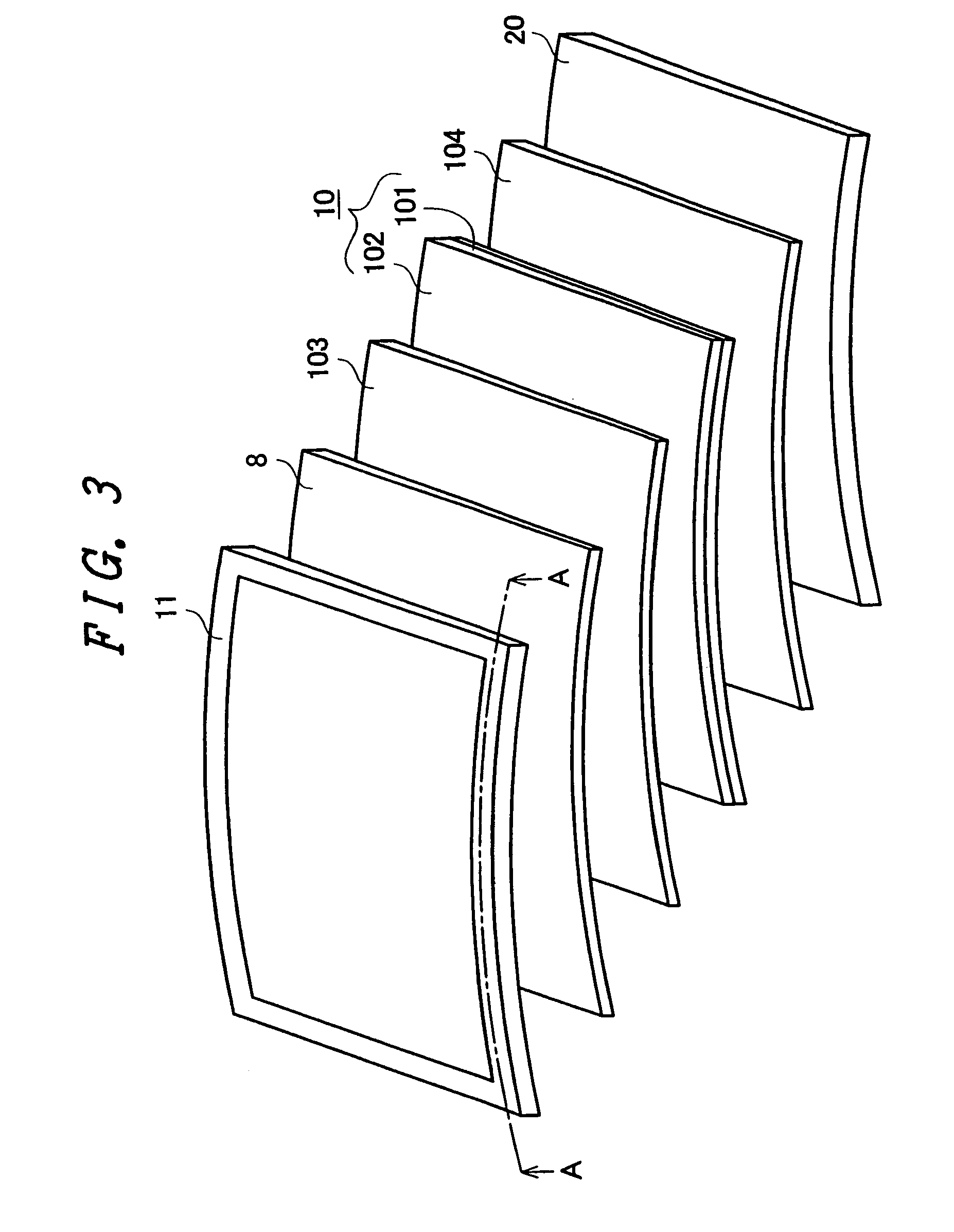
[0054]FIG. 1 is a view of appearance of a crystal display device of an embodiment 1. FIG. 1 shows a display in which the screen is formed convex outwardly. The display device of this kind is used for amusement purposes, e.g., used in the game machines such as slot game machines. In FIG. 1, a liquid crystal display panel 10 is curved outwards. The liquid crystal display panel 10 curved outwards includes a substrate which in this embodiment is formed by using a glass. That is, the glass substrate is formed having a decreased thickness enabling the liquid crystal display panel 10 to be easily curved, and is held in a frame 11 having a curved surface to thereby form the liquid crystal display panel 10 having a curved screen. Though not shown in FIG. 1, the upper side of the liquid crystal display panel 10 is covered with a transparent surface cover 8. That is, the surface cover 8 is provided between the frame 11 and the liquid crystal display panel 10.
[0055]In FIG. 1, the liquid crystal...
embodiment 2
[0081]The embodiment 1 has dealt with the case where the screen of the liquid crystal display device was convex outwards. The advantage of the invention utilizing the liquid crystal display device is that the liquid crystal display device can be formed even when the screen has a concave shape. When the screen has the concave shape, the liquid crystal display device exhibits its features more conspicuously.
[0082]FIG. 7 illustrates viewing angle range characteristics of a general liquid crystal display panel having a flat display surface. One of the problems concerning the image quality of the liquid crystal display device is that the brightness and chromaticity vary depending upon the angle of viewing the screen. FIG. 7 illustrates viewing angle range characteristics of a liquid crystal display device of an ordinary TN system. In. FIG. 7, the ordinate represents the brightness. The brightness of the screen when it is viewed from a direction perpendicular thereto is regarded to be 100...
embodiment 3
[0096]Embodiments 1 and 2 have dealt with the cases where the glass substrates were polished to decrease the thicknesses thereof to impart curvature thereto. Referring to FIG. 2A, on the other hand, when the display surface has a sufficiently large radius of curvature, the curvature can be imparted without the need of decreasing the thicknesses of the glass substrates by polishing. From FIG. 2A, for example, if the radius of curvature is not smaller than one meter, a curved surface can be formed by the invention even if the liquid crystal display panel 10 has a thickness of about 1 mm. Such a large curvature may be that of the case of a liquid crystal display device for use with TVs.
[0097]When such a large curvature is to be imparted as in this embodiment, the thicknesses of the TFT substrate 101 and the color filter substrate 102 can be decreased to be about 0.5 mm, respectively, even when the surface of the liquid crystal display panel 10 is to be curved by the frame 11 and the li...
PUM
| Property | Measurement | Unit |
|---|---|---|
| thickness | aaaaa | aaaaa |
| thickness | aaaaa | aaaaa |
| thickness | aaaaa | aaaaa |
Abstract
Description
Claims
Application Information
 - R&D
- Intellectual Property
- Life Sciences
- Materials
- Tech Scout
- Unparalleled Data Quality
- Higher Quality Content
- 60% Fewer Hallucinations
Browse by: Latest US Patents, China's latest patents, Technical Efficacy Thesaurus, Application Domain, Technology Topic, Popular Technical Reports.
© 2025 PatSnap. All rights reserved.Legal|Privacy policy|Modern Slavery Act Transparency Statement|Sitemap|About US| Contact US: help@patsnap.com


