Brushless electric machine with stationary shaft and method of making same

a technology of stationary shaft and brushless electric machine, which is applied in the direction of mechanical energy handling, magnetic circuit rotating parts, magnetic circuit shape/form/construction, etc., can solve the problems of limiting the rotational speed at which the alternator can rotate, undesirable mass, and undesirable inertia of the rotational components of the assembly

Active Publication Date: 2011-04-05
BORGWARNER INC
View PDF12 Cites 7 Cited by
  • Summary
  • Abstract
  • Description
  • Claims
  • Application Information

AI Technical Summary

Problems solved by technology

The cantilevered poles, however, limit the rotational speed at which the alternator can rotate.
This rotational speed limitation is partially due to radially outward flexing of the pole segments that results from the high centrifugal forces on the pole segments that occurs at high rotational speeds, which can result in undesirable contact of the flexed pole segments with the stator.
Efforts to control such flexing usually add undesirable mass, and consequently, undesirable inertia to the rotational components of the assembly.

Method used


Image

  • Brushless electric machine with stationary shaft and method of making same
  • Brushless electric machine with stationary shaft and method of making same
  • Brushless electric machine with stationary shaft and method of making same

Examples


Embodiment Construction

[0009]A detailed description of several embodiments of the disclosed apparatus and method are presented herein by way of exemplification and not limitation with reference to the Figures.

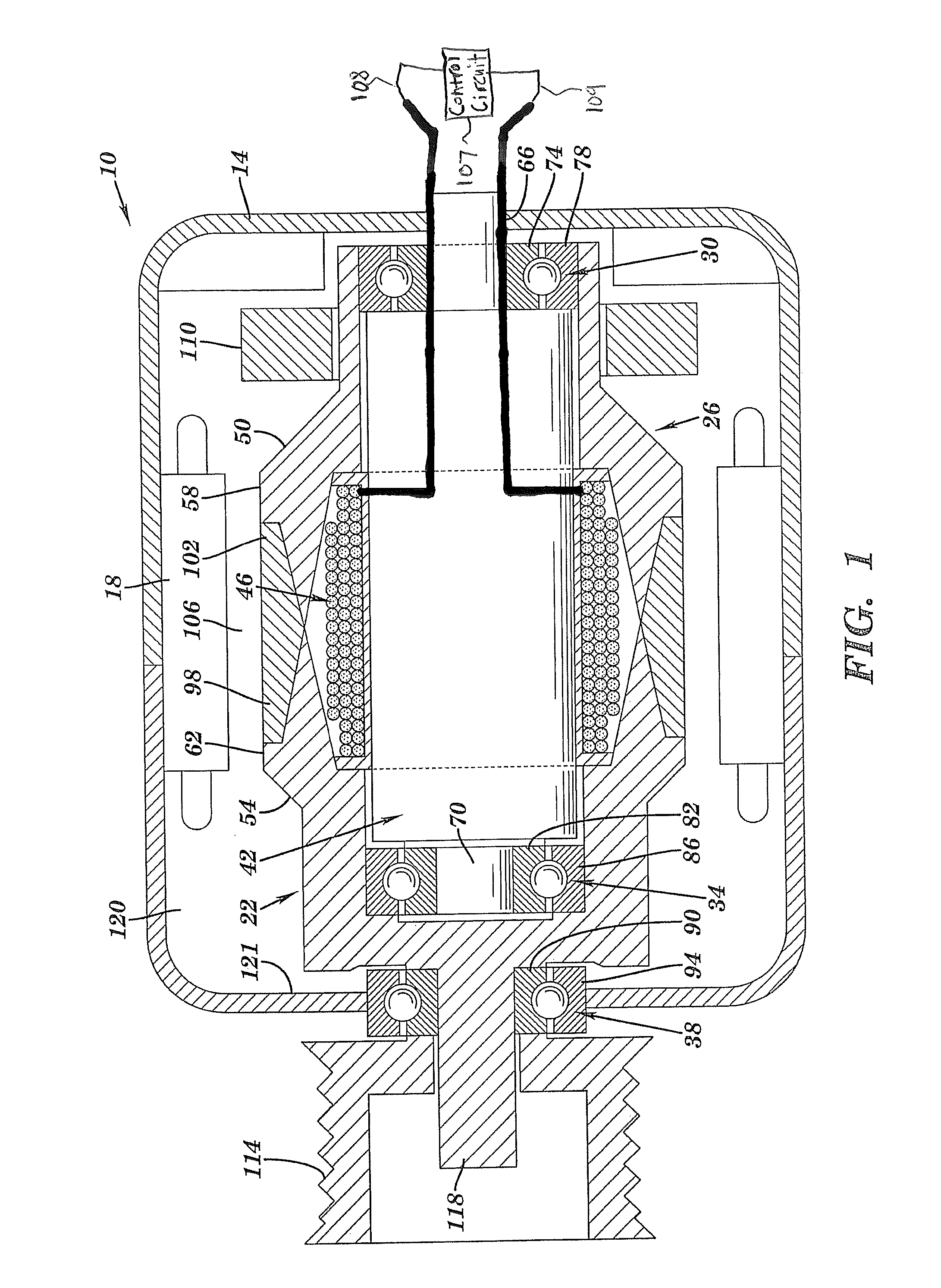
[0010]Referring to FIG. 1, the electric machine, disclosed herein as brushless alternator 10, is illustrated in cross section. Although described as an alternator, the electric machine disclosed herein may be any electric machine, such as a motor or starter-generator, for example. The brushless alternator 10 includes, a housing 14, a stator 18, a rotor 22, a pole assembly 26, and three bearings 30, 34, and 38. The rotor includes a stationary shaft 42 with a field coil 46 attached therearound. Unlike typical pole assemblies for brushless alternators, the pole assembly 26 disclosed herein is not cantilevered about a shaft and a field coil. Instead the pole assembly 26 has two pole pieces 50, 54 that are assembled axially from either end of the shaft 42. The pole pieces 50, 54 each include a plurality o...


PUM

PropertyMeasurementUnit
currentaaaaaaaaaa
rotational speedaaaaaaaaaa
rotational speedsaaaaaaaaaa

Abstract

Disclosed herein is an electric machine. The electric machine includes, a housing defining an internal volume, a stationary shaft fixedly attached to the housing, a stationary field coil attached to the shaft, a pole assembly rotatable about the shaft, and a pulley fixedly attached to the pole assembly being positioned externally of the internal volume.

Description

BACKGROUND OF THE INVENTION[0001]Many of the advantages that brushless electric machines such as alternators, for example, have over brush type alternators result from the use of a stationary field coil. An electric machine with a stationary field coil does not require sliding electrical contacts such as brushes and commutators. Having a stationary field coil, however, necessitates that pole segments, of pole pieces, rotate in close proximity to the stationary field coil. Typically the pole segments are positioned radially outwardly of the field coil and radially inwardly of a stator with small annular air gaps therebetween. Since a brushless alternator has no sliding contacts, current to the field coil is typically supplied through stationary conductors routed through an axial end of the machine to the field coil; typically this is the same axial end that structurally supports the field coil. In such a design the rotatable poles are fixedly attached to the shaft and the pole segmen...

Claims


Application Information

Patent Timeline
Patent Type & Authority Patents(United States)
IPC IPC(8): H02K7/08
CPCH02K7/08H02K19/24H02K7/085Y10T29/49009H02K21/40H02K7/088
Inventor NEET, KIRKYORK, MICHAEL T.
Owner BORGWARNER INC
Why Eureka
Try Eureka