
Surface shape measuring apparatus and surface shape measuring method

a technology of surface shape and measuring apparatus, which is applied in the direction of mechanical measurement arrangements, mechanical roughness/irregularity measurements, instruments, etc., can solve the problems of damage or contamination of the probe tip, measurement operation cannot be stopped immediately by detecting this out-of-range condition, and the laboriousness of measurement work, so as to achieve the effect of simplifying the measurement work

Active Publication Date: 2011-04-05
TOKYO SEIMITSU
View PDF14 Cites 8 Cited by
  • Summary
  • Abstract
  • Description
  • Claims
  • Application Information

AI Technical Summary

Benefits of technology

The present invention has been devised in view of the above problems, and an object of the invention is to enhance the measurement work efficiency by eliminating the need to specify the measurement length when measuring the surface shapes of workpieces having different measurement ranges.
In this way, by monitoring the amount of displacement of the probe detected during the measurement and determining whether the probe has reached the measurement end point, the measurement work can be simplified by eliminating the need to specify the measurement length required in the prior art.

Problems solved by technology

As a result, when measuring the surfaces of workpieces differing in size or shape one after another, the operator has had to specify the sliding movement length L over again for each workpiece, and the operation for such specification has made the measurement work very laborious.
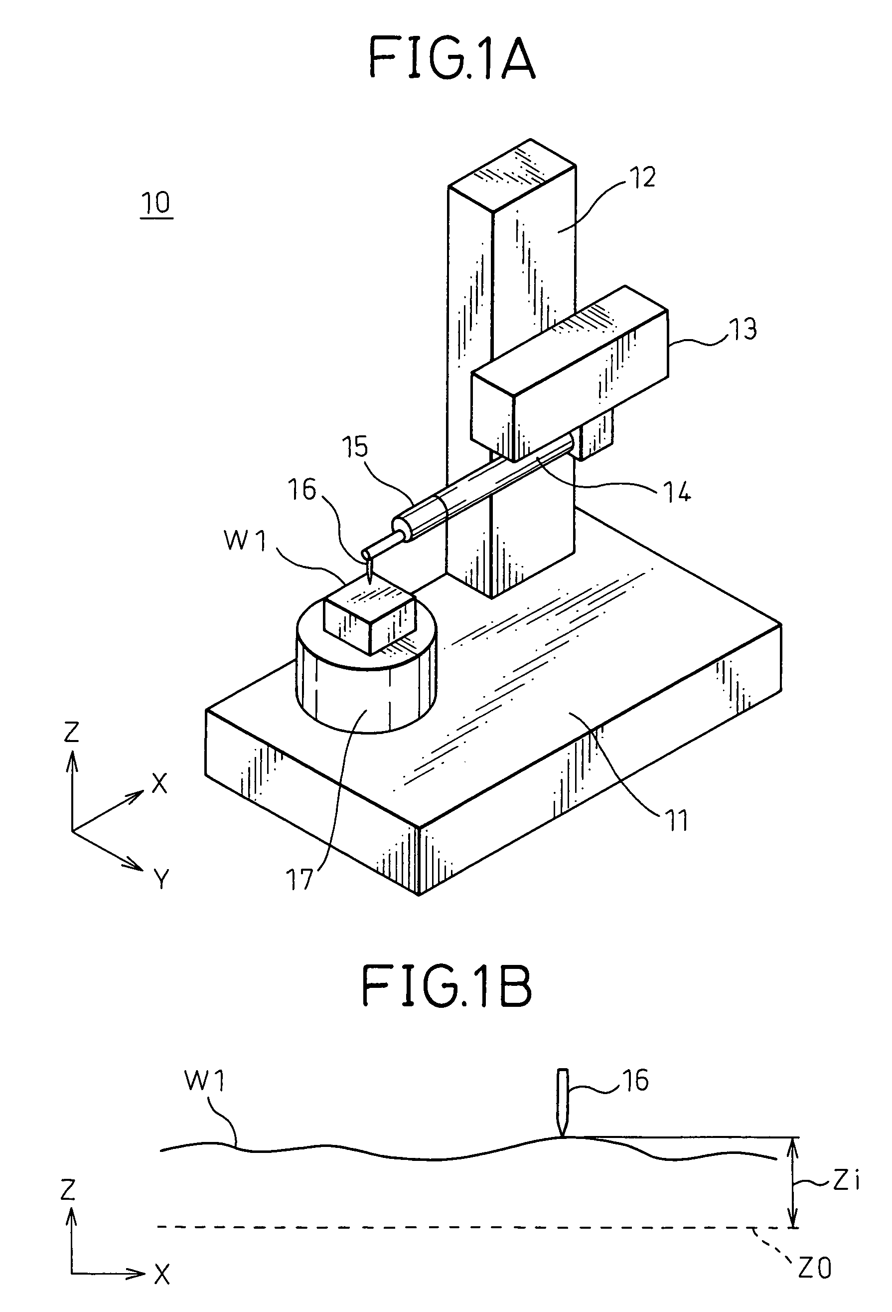
With this method; however if the probe 16 has gone off the surface of the workpiece, the measurement operation cannot be stopped immediately by detecting this out-of-range condition.
As a result, when measuring the surface roughness of a thin workpiece such as a piston ring, for example, the probe 16 may be dropped onto the work table, damaging or contaminating the tip of the probe 16.

Method used


Image

  • Surface shape measuring apparatus and surface shape measuring method
  • Surface shape measuring apparatus and surface shape measuring method
  • Surface shape measuring apparatus and surface shape measuring method

Examples


Embodiment Construction

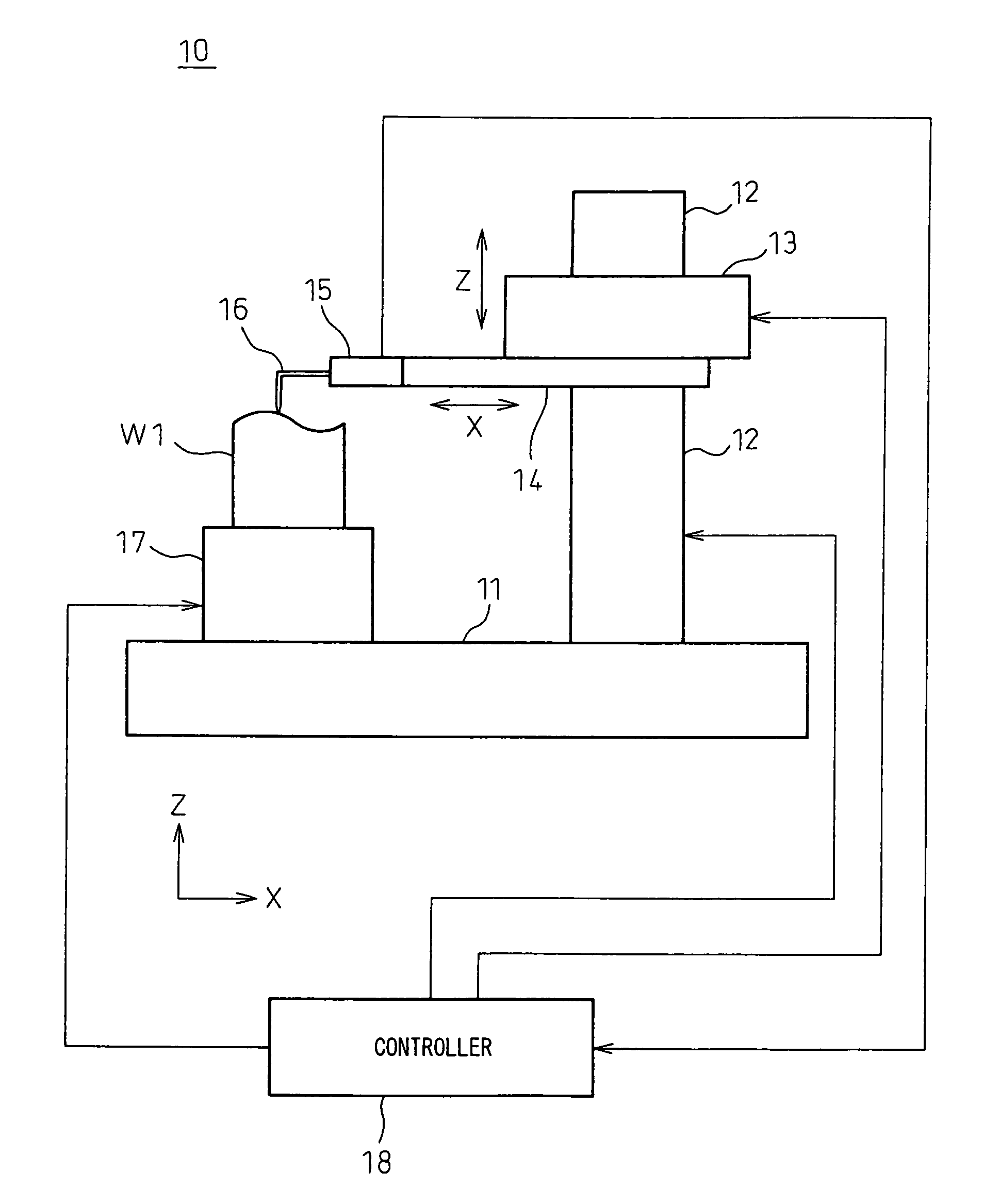
FIG. 5 is a diagram showing the general configuration of a surface roughness / shape measuring apparatus according to an embodiment of the present invention. The surface roughness / shape measuring apparatus 10, just like the configuration described with reference to FIG. 1A, comprises a base 11, a column 12 installed vertically on the base 11, a Z-direction moving part 13 slidably supported on the column 12, an X-arm 14 horizontally supported on the Z-direction moving part 13, a displacement detector 15 attached to the tip of the X-arm 14, a stylus 16 as a probe whose displacement in the Z-axis direction is detected by the displacement detector 15, and a work table 17, installed on the base 11, for mounting thereon a workpiece W1.

The surface roughness / shape measuring apparatus 10 further comprises a controller 18 which controls the measurement operation of the surface roughness / shape measuring apparatus 10 by outputting control signals to driving means for driving the various moving me...


PUM


Abstract

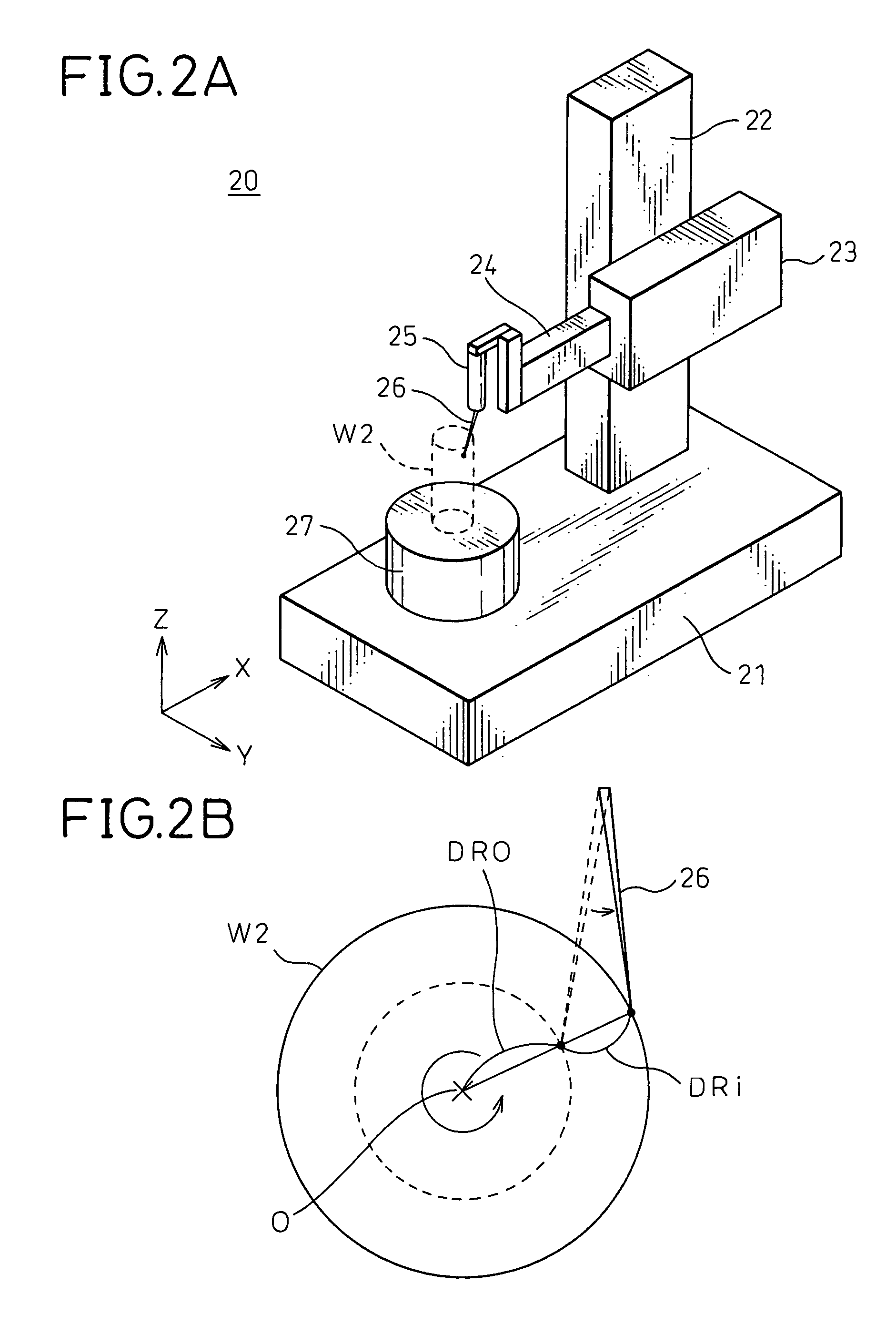
In a surface shape measurement device that measures the surface shape of a sample (W1, W2) by moving a probe (16, 26) in a sliding fashion along the surface of the sample (W1, W2) and thereby detecting the amount of displacement of the probe (16, 26) caused by irregularities on the surface, an initial amount of displacement is detected which is the amount of displacement of the probe (16, 26) when the probe is first placed in contact with a measurement start point on the surface of the sample (W1, W2), and the amount of displacement of the probe (16, 26), detected as it is moved in a sliding fashion along the surface, is compared with the initial amount of displacement to determine whether the probe (16, 26) has reached a measurement end point.

Description

CROSS-REFERENCE TO RELATED APPLICATIONThis application is a National Phase Patent Application and claims the priority of International Application Number PCT / JP2008 / 059757, filed on May 21, 2008, which claims priority of Japanese Patent Application Number 2007-172955, filed on Jun. 29, 2007.TECHNICAL FIELDThe present invention relates to a surface shape measuring apparatus, such as a surface roughness / shape measuring apparatus or a roundness measuring apparatus, that measures the surface shape of a sample by moving a probe in a sliding fashion along the surface of the sample and thereby detecting the amount of displacement of the probe caused by irregularities on the surface. More specifically, the invention relates to a technique for determining the measurement end point on the surface of the sample at which the sliding movement of the probe is to be stopped in the surface shape measurement.BACKGROUND ARTA surface roughness / shape measuring apparatus or a roundness measuring apparat...

Claims


Application Information

Patent Timeline
Patent Type & Authority Patents(United States)
IPC IPC(8): G01B5/20G01B5/28
CPCG01B5/28G01B5/20
Inventor ISHIKAWA, YASUNARI
Owner TOKYO SEIMITSU
Learn More