Ground clearing apparatus

a technology for ground clearing and equipment, applied in mechanical machines/dredgers, soil shifting machines/dredgers, transportation and packaging, etc., can solve the problems of high labor intensity, high cost, and inability to maintain an inventory of such a wide range of implements

Inactive Publication Date: 2011-03-29
BEAM ROGER D +2
View PDF6 Cites 20 Cited by
  • Summary
  • Abstract
  • Description
  • Claims
  • Application Information

AI Technical Summary

Benefits of technology

[0009]The problem of performing multiple ground clearing operations with a single attachable implement is solved by a ground clearing apparatus comprising a box member comprised of a framework having a perimeter comprised of an upper edge, first and second side edges, and a lower edge; a plurality of base teeth protruding downwardly from the lower edge; a first hinge ear joined to the framework proximate to the upper edge and first side edge; and a second hinge ear joined to the framework proximate to the upper edge and second side edge; and a grapple comprised of a first grapple arm hingeably attached to the first hinge ear of the box member; a second grapple arm hingeably attached to the second hinge ear of the box member; and a cross member joined to a distal end of the first grapple arm and to a distal end of the second grapple arm, and a plurality of grapple teeth extending outwardly from the cross member, the grapple being movable from a closed position in which the cross member is proximate to the lower edge of the box member to an open position. When the grapple is in the closed position, the grapple teeth are interspersed with the base teeth, and the apparatus may be used as a fine rake. When the grapple is in the open position, only the base teeth are in contact with the ground to be cleared, and the apparatus may be used as a coarse rake.

Problems solved by technology

Maintaining an inventory of such a range of implements is expensive, as is transporting all of these implements to a job site when they are needed.
During a ground clearing operation, the numerous changeovers from one implement to another that are required to perform the full range of ground clearing operations is labor intensive, and therefore also costly.

Method used


Image

  • Ground clearing apparatus
  • Ground clearing apparatus
  • Ground clearing apparatus

Examples


Embodiment Construction

[0032]For a general understanding of the present invention, reference is made to the drawings. In the drawings, like reference numerals have been used throughout to designate identical elements.

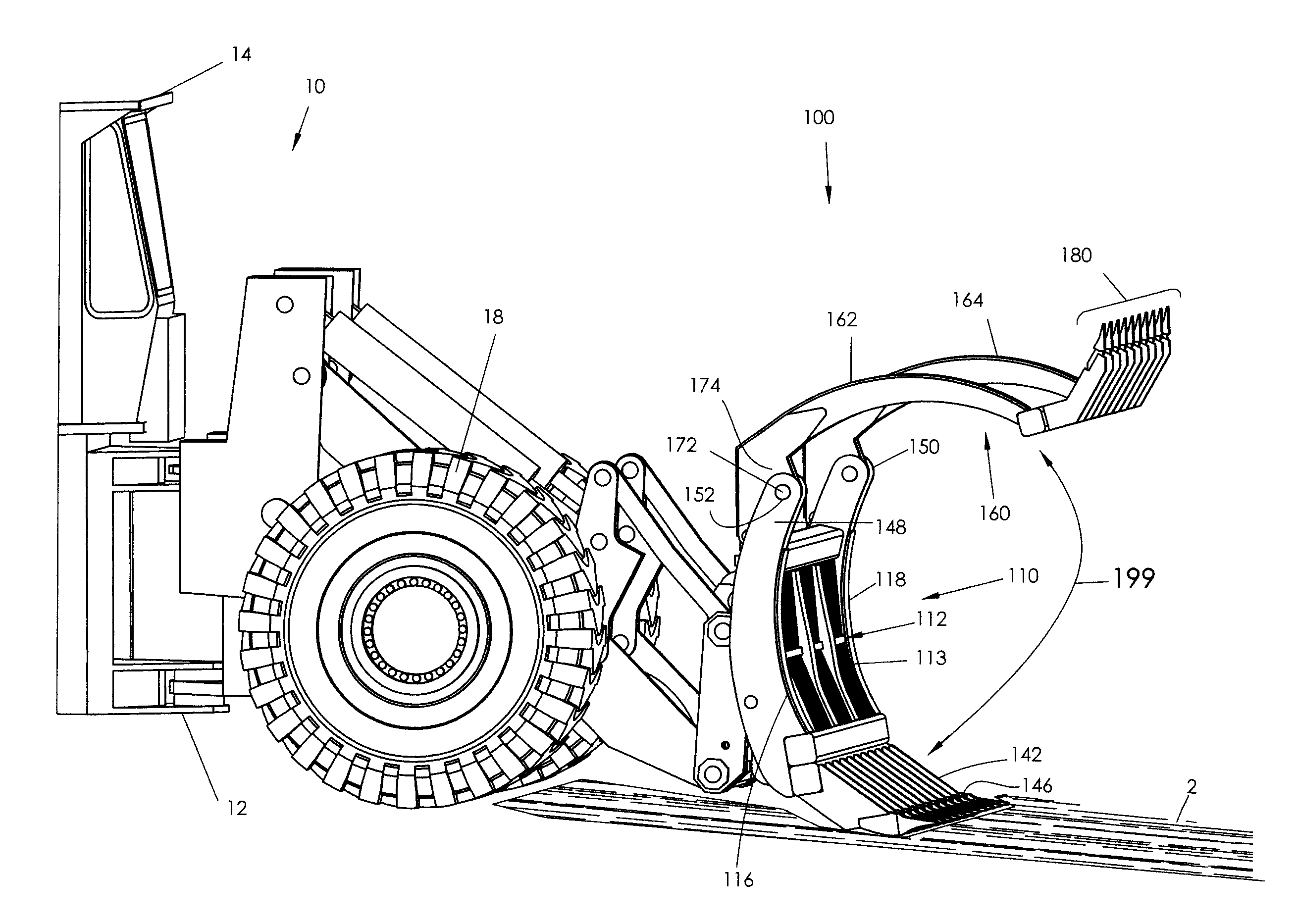
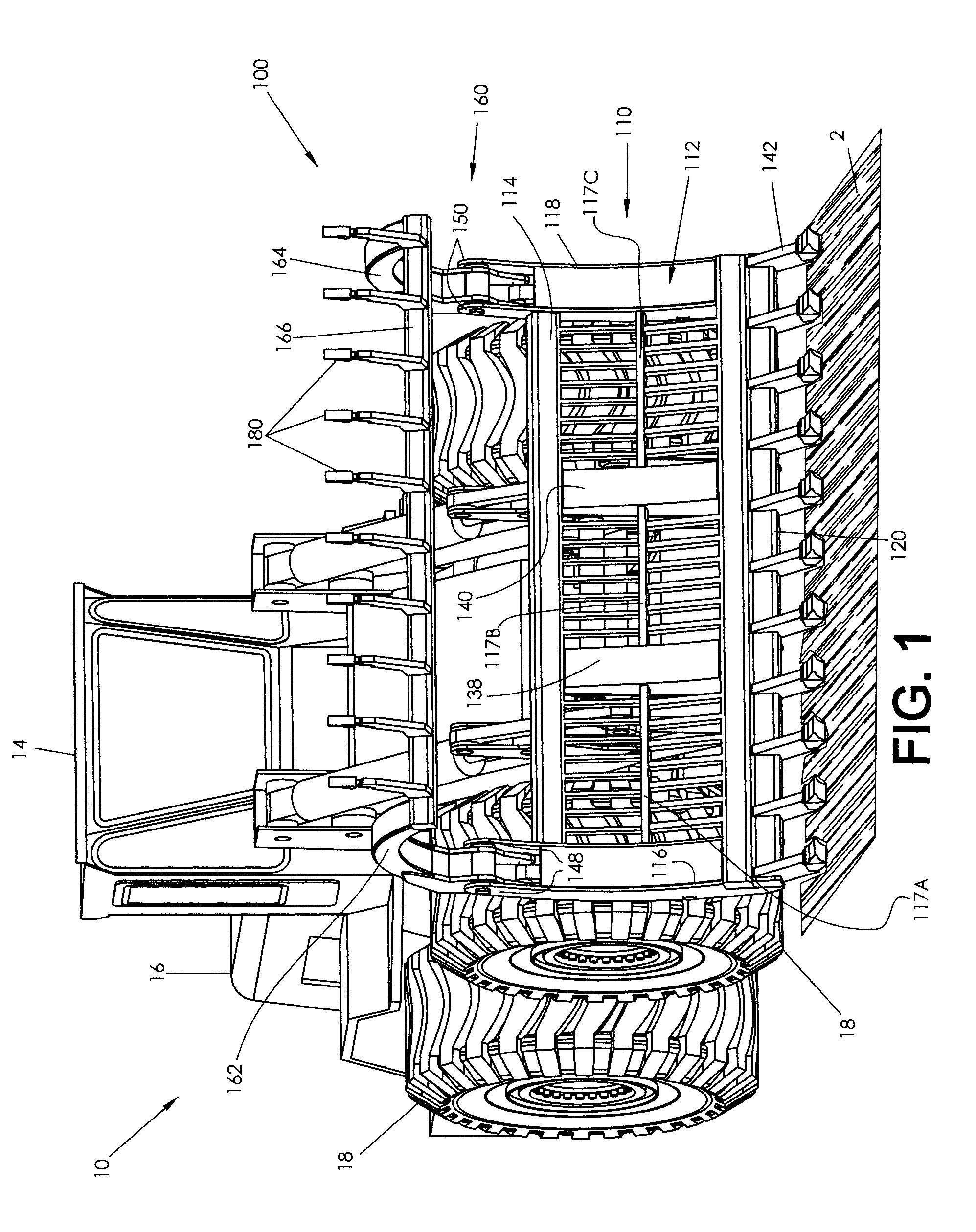
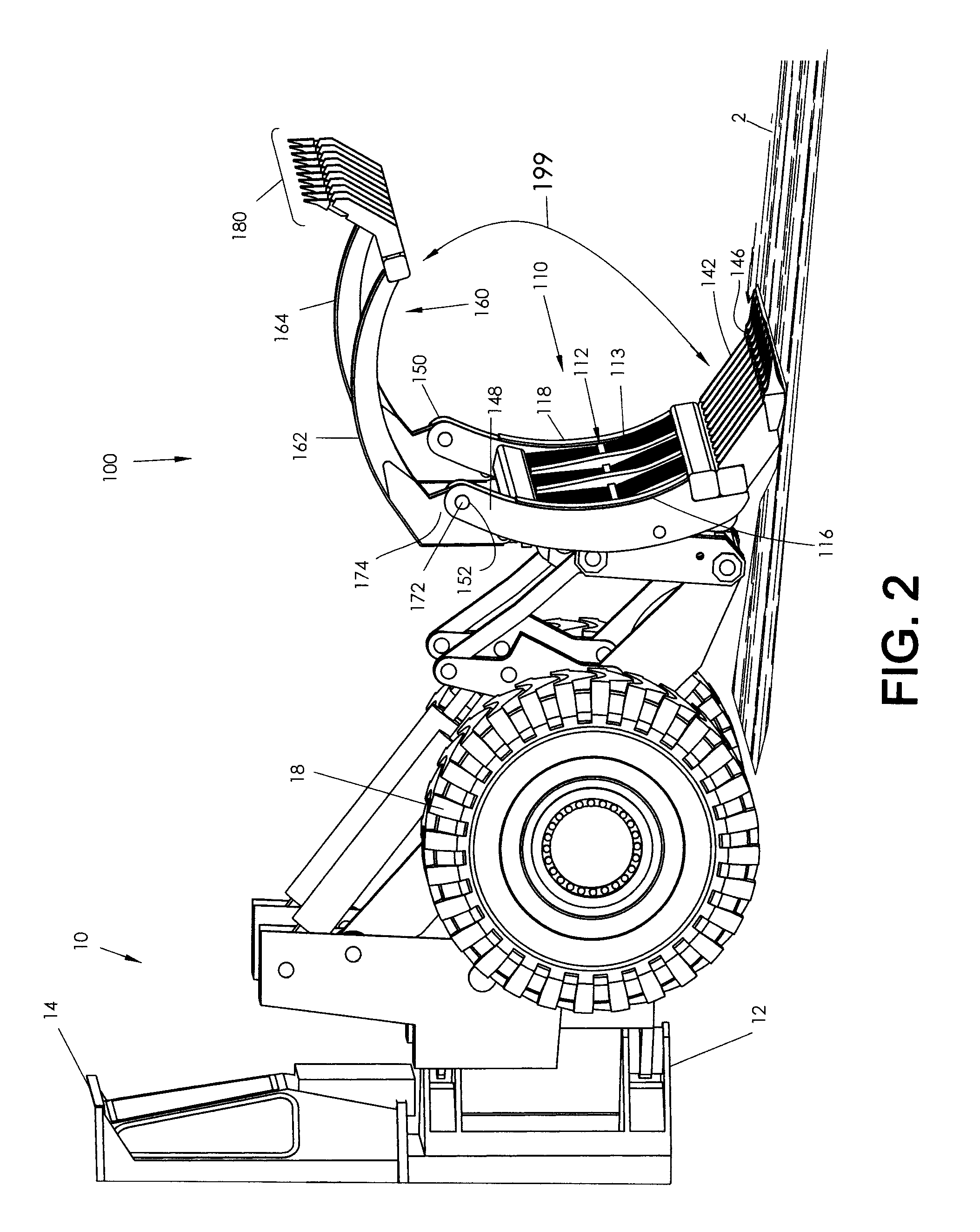
[0033]In accordance with the present disclosure, a ground clearing apparatus is provided comprising a box member and a grapple. The box member and the grapple may each include teeth for raking of ground to be cleared. The apparatus may further include first and second support arms, which may be operatively connected to a tractor, a loader, a bulldozer, or a skid-steer. The apparatus is useful in performing the ground clearing functions of knocking over trees and stumps, dislodging trees, stumps, and brush from the ground, ripping roots and rocks from the ground and bringing them to the surface, breaking up sod and busting clumps of sod / soil, and raking the ground to select and separate rocks and roots from the ground, and picking up rocks, trees, stumps, etc., and removing them to a remote lo...


PUM


Abstract

A ground clearing apparatus comprising a box member comprised of a framework having an upper edge, first and second side edges, and a lower edge. A plurality of base teeth protrude downwardly from the lower edge. The apparatus further comprises a grapple including a first grapple arm hingeably attached to the box member, a second grapple arm hingeably attached to the box member, and a cross member joined to a distal ends of the first and second grapple arms. A plurality of grapple teeth extend outwardly from the cross member. The grapple is movable from a closed position in which the grapple teeth are interspersed with the base teeth, to an open position in which the grapple teeth are separated from the base teeth.

Description

CROSS-REFERENCE TO RELATED PATENT APPLICATIONS[0001]This application claims priority to U.S. provisional patent application Ser. No. 61 / 176,867, filed May 8, 2009, the disclosure of which is incorporated herein by reference.BACKGROUND[0002]1. Field of the Invention[0003]Ground clearing apparatus that is attachable to a loader, bulldozer, or tractor, and includes a combination of ripping, raking, and gripping elements for extracting and separating rocks, and roots, stumps, and other vegetation components from soil.[0004]2. Description of Related Art[0005]The clearing of rocks and / or vegetation from various landscapes requires powerful, robust machinery. This is typically accomplished through the use of bulldozers, loaders, or tractors, to which is attached one or more modular implements which can be used to perform a ground clearing function. The type of ground clearing functions may vary, depending upon the intended use of the cleared ground. Common uses of newly cleared ground are ...

Claims


Application Information

Patent Timeline
Patent Type & Authority Patents(United States)
IPC IPC(8): E02F3/96B66C21/00
CPCA01G23/06E02F3/404E02F3/4133E02F5/32
Inventor BEAM, ROGER D.BEAM, RICHARD H.BEAM, MICHAEL M.
Owner BEAM ROGER D
Why Eureka
Try Eureka