
Camera module and electronic apparatus provided with it

a technology of electronic equipment and camera module, which is applied in the direction of instruments, television systems, and television system scanning details, can solve the problems of inability to deal with macro shots, inability to obtain beautiful images, and inability to automatically focus and control functions of conventional camera modules, etc., to achieve beautiful images over an entire image region, small and thin

Active Publication Date: 2011-03-22
PANASONIC INTELLECTUAL PROPERTY CORP OF AMERICA
View PDF18 Cites 7 Cited by
  • Summary
  • Abstract
  • Description
  • Claims
  • Application Information

AI Technical Summary

Benefits of technology

The present invention relates to a camera module that is small and thin with an automatic focusing control function and can handle landscape, portrait, and macro shots. The camera module includes an imaging system with multiple lens portions and optical filters that transmit light in different wavelength ranges. The space between the optical axes of the lens portions is set to minimize color shifting of the image of an object at an infinite distance. The invention solves the problem of conventional camera modules not having automatic focusing control function and being unable to handle macro shots.

Problems solved by technology

However, this conventional camera module has no automatic focusing control function.
Therefore, although this conventional camera module can deal with landscape shots and portrait shots, it cannot deal with macro shots.
Therefore, color irregularities are generated in the region of the person N, so that a beautiful image cannot be obtained.

Method used


Image

  • Camera module and electronic apparatus provided with it
  • Camera module and electronic apparatus provided with it
  • Camera module and electronic apparatus provided with it

Examples


embodiment 1

[0106]A camera module according to Embodiment 1 of the present invention achieves a beautiful image over an entire image region by detecting edges, performing a division into blocks and performing a parallax correction based on the parallax for each block. Also, by making a coarse adjustment by an automatic focusing control based on the parallax and a fine adjustment by an automatic focusing control based on a highly accurate contrast, it is possible to carry out a highly accurate automatic focusing control at a high speed. Furthermore, an amount of the fine adjustment is learned so as to improve the accuracy of the next coarse adjustment.

[0107]The camera module according to Embodiment 1 of the present invention will be described, with reference to the accompanying drawings.

[0108]FIG. 1 is a sectional view showing a configuration of the camera module according to Embodiment 1 of the present invention. In FIG. 1, a camera module 101 includes a lens module portion 110 and a circuit po...

embodiment 2

[0205]A camera module according to Embodiment 2 of the present invention achieves a beautiful image with a reduced parallactic influence over an entire image region by detecting a parallax of an edge using contrasts of a plurality of images, computing a parallax of the entire image region based on that parallax, performing an image synthesis so as to reduce a parallactic influence based on this parallax and performing a parallax correction.

[0206]The camera module according to Embodiment 2 of the present invention will be described, with reference to the accompanying drawings.

[0207]FIG. 19 is a sectional view showing a configuration of the camera module according to Embodiment 2 of the present invention. The configuration is similar to that of Embodiment 1 except for an SLSI 225 of a circuit portion 220 of a camera module 201. Members similar to those in Embodiment 1 are assigned the same reference numerals, and the description thereof will be omitted.

[0208]FIG. 20 is a block diagram...

embodiment 3

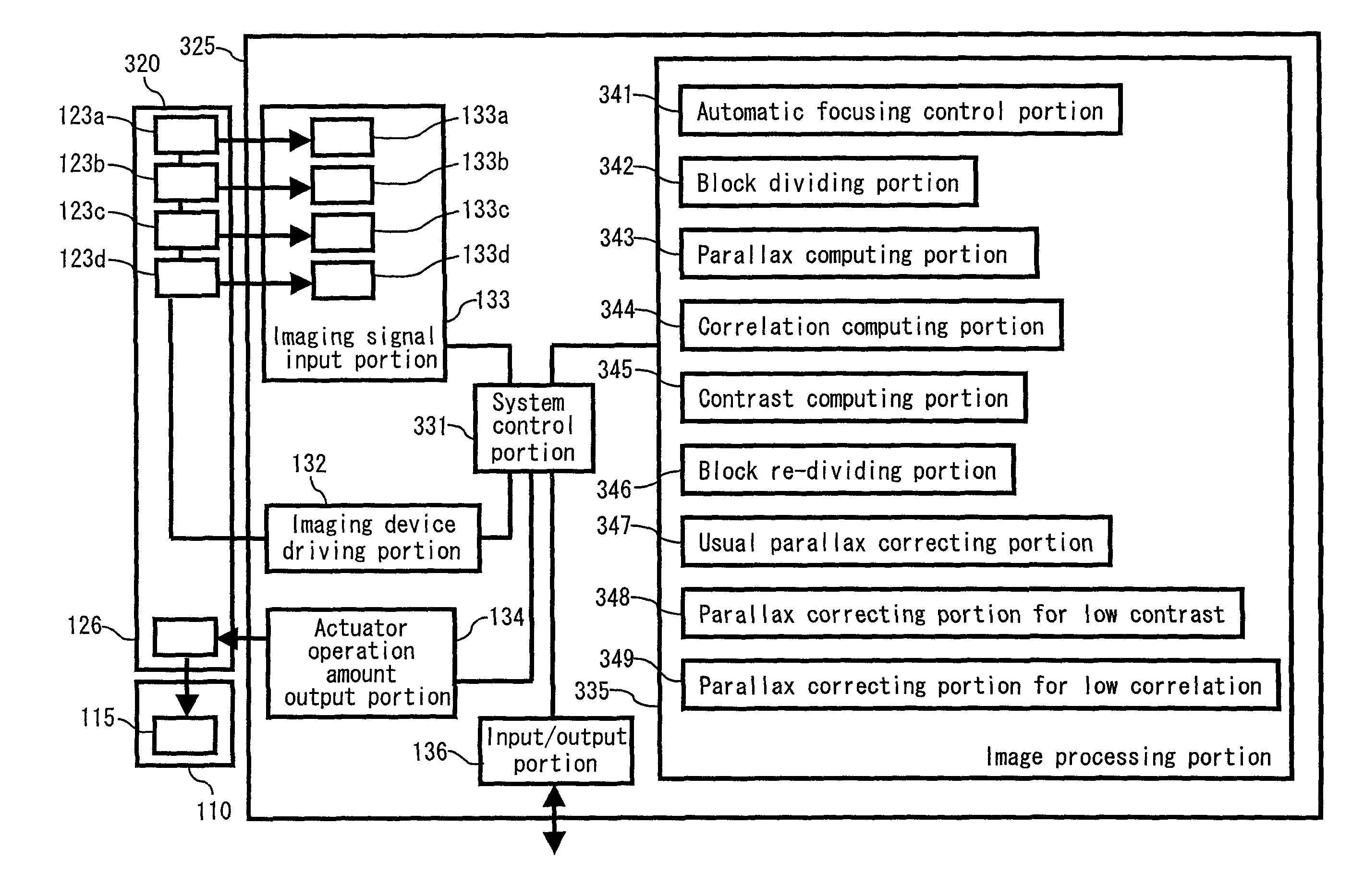
[0236]A camera module according to Embodiment 3 of the present invention divides an imaging region into blocks, computes a parallax for each block and evaluates the parallax based on a contrast value computed for each block and a correlation of an image shifted by the parallax. When the correlation is high and the contrast is high, the computed parallax is judged to be appropriate, and a usual parallax correction is performed based on the parallax. When the correlation is low and the contrast is low, the computed parallax is judged not to be accurate, and a parallax correction for low contrast is performed. Further, when the correlation is low and the contrast is high, it is judged that the computed parallax is not appropriate because subjects at plural distances are contained, and the blocks are re-divided. In this way, a beautiful image over an entire image region is obtained.

[0237]In the following, the camera module according to Embodiment 3 of the present invention will be descr...


PUM


Abstract

A camera module that can be made thinner and achieves a beautiful image over an entire image region regardless of a subject distance is provided. The camera module includes a plurality of lens portions, each including at least one lens, a plurality of imaging regions, provided in one-to-one correspondence with the plurality of lens portions, each including a light-receiving surface that is substantially orthogonal to an optical axis direction of its corresponding lens portion, an imaging signal input portion to which a plurality of imaging signals outputted respectively from the plurality of imaging regions are inputted, a block division portion for dividing at least one imaging signal of the plurality of imaging signals into a plurality of blocks, a parallax computing portion for computing for each of the blocks a parallax between images formed respectively by the plurality of lens portions using the imaging signal, and a parallax correcting portion for correcting the plurality of imaging signals based on the parallax and performing an image synthesis.

Description

TECHNICAL FIELD[0001]The present invention relates to a camera module that is small and thin and has an automatic focusing control function, and an electronic apparatus including this camera module.BACKGROUND ART[0002]As a conventional camera module, a camera module is described in JP 2001-78213 A. FIG. 47 is a sectional view showing a configuration of the camera module described in JP 2001-78213 A.[0003]In FIG. 47, an imaging system 9010 is an optical processing system that directs light from an object through a diaphragm 9110 and an imaging lens 9100 and forms an image on an imaging surface of an imaging device 9120. The diaphragm 9110 has three circular apertures 9110a, 9110b and 9110c. Light from the object that has left the apertures 9110a, 9110b and 9110c respectively and entered an incident surface 9100e of the imaging lens 9100 leaves three lens portions 9100a, 9100b and 9100c of the imaging lens 9100 and then forms three object images on the imaging surface of the imaging d...

Claims


Application Information

Patent Timeline
Patent Type & Authority Patents(United States)
IPC IPC(8): H04N5/247H04N23/90H04N23/13
CPCH04N3/1593H04N5/2254H04N5/2257H04N5/23212H04N5/23232H04N5/2351H04N9/045H04N9/09H04N9/093H01L2924/16195H01L2224/48091H01L2224/45144H04N23/57H04N23/55H04N23/673H04N23/951H04N23/71H04N25/41H04N23/15H04N23/13H04N25/134H01L2924/00014H01L2924/00
Inventor IIJIMA, TOMOKUNIISHIKAWA, TAKASHINUMAI, IKUOHAYAKAWA, MASAHITOTAKAI, AKI
Owner PANASONIC INTELLECTUAL PROPERTY CORP OF AMERICA
Learn More