
Multi-band radiating elements with composite right/left-handed meta-material transmission line

a transmission line and meta-material technology, applied in the field of communication antennas, can solve the problems of difficult determination of placement and the number of required shorting pins, increase in physical size requirements,

Active Publication Date: 2011-03-22
RGT UNIV OF CALIFORNIA
View PDF31 Cites 270 Cited by
  • Summary
  • Abstract
  • Description
  • Claims
  • Application Information

AI Technical Summary

Benefits of technology

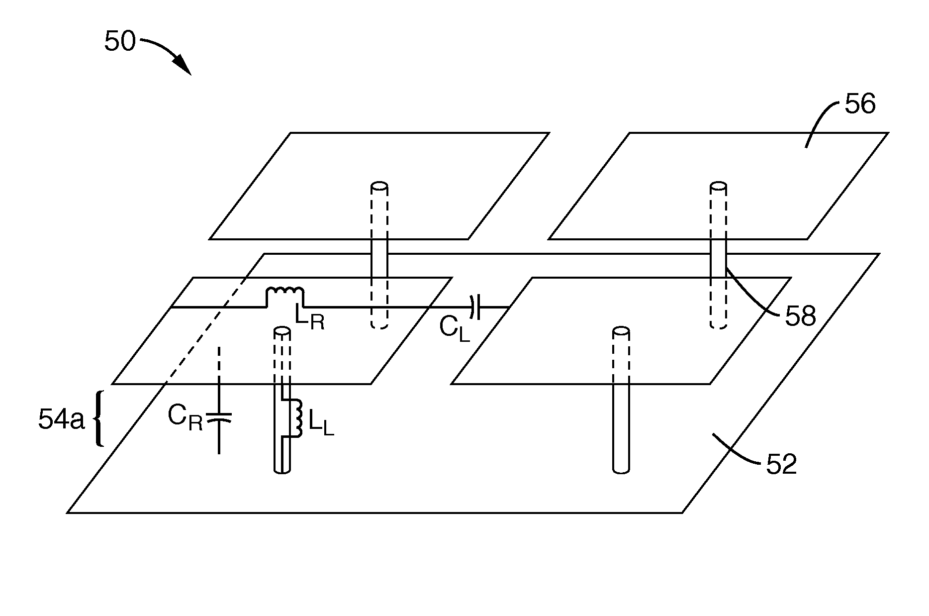
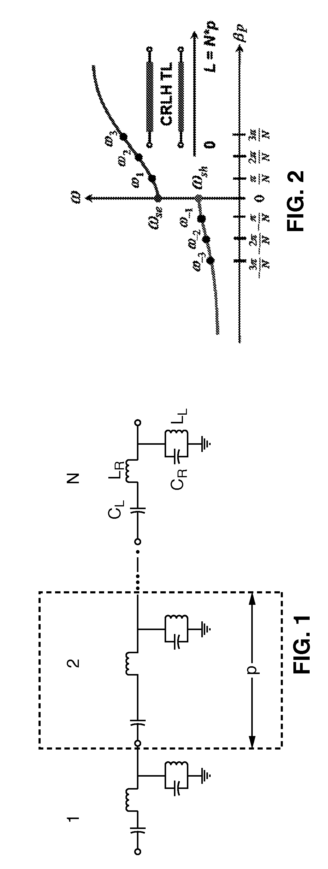
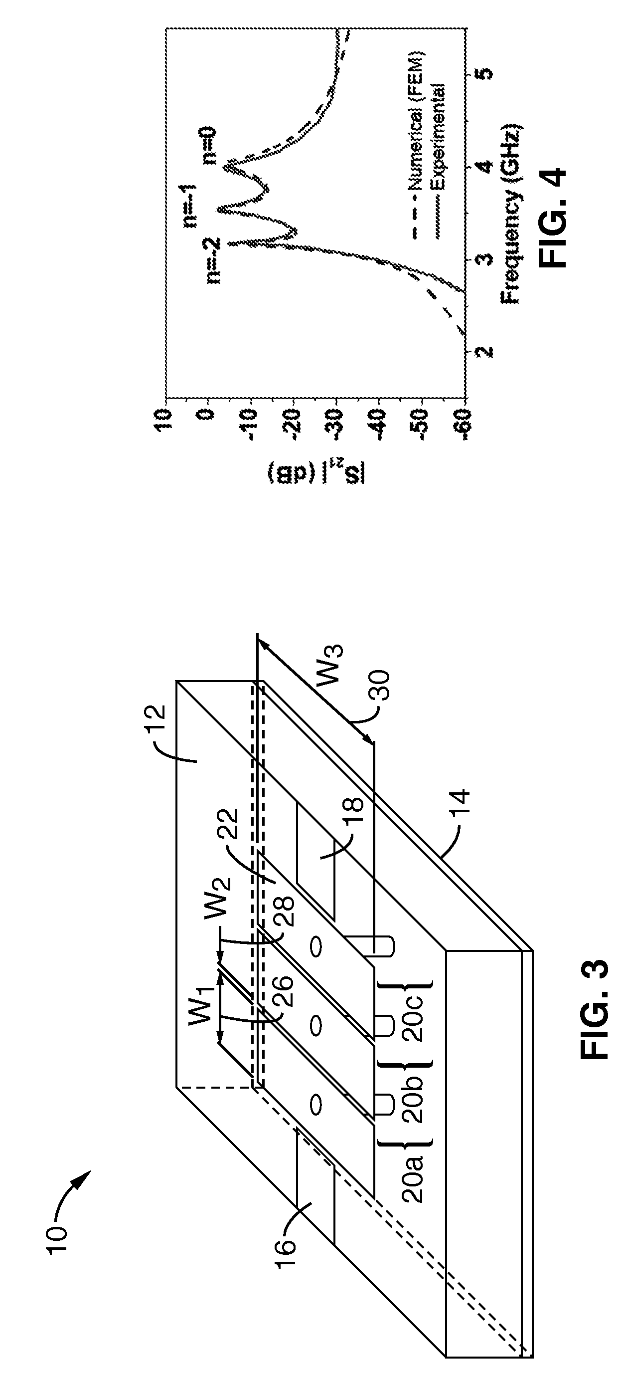
The invention is a new type of antenna that solves the problems of conventional dual-band and multi-band antennas. It uses a composite right / left-handed (CRLH) meta-material transmission line (TL) that has unique properties such as nonlinear dispersion relation and infinite wavelength. The antenna has several advantages such as being compact, having a small physical size, and supporting a wide range of frequencies. The CRLH TL can be designed to have a nonlinear dispersion relation, which makes it easier to control the operational frequencies. The antenna can be used in various applications such as microwave and millimeter-wave communications. The invention also provides a multi-mode resonant radiating element that can operate at multiple radio frequency bands. Overall, the invention offers a new solution for designing compact, efficient, and versatile antennas.

Problems solved by technology

These dual-band methods have additional drawbacks, including that the operational frequencies are limited to integer multiples of the fundamental mode by operating at different harmonics, while the physical size requirement increases when adding another resonator.
In the case of reactive loading, the placement and the number of required shorting pins is not easily determined.

Method used


Image

  • Multi-band radiating elements with composite right/left-handed meta-material transmission line
  • Multi-band radiating elements with composite right/left-handed meta-material transmission line
  • Multi-band radiating elements with composite right/left-handed meta-material transmission line

Examples


Embodiment Construction

[0088]Referring more specifically to the drawings, for illustrative purposes the present invention is embodied in the apparatus generally shown in FIG. 1 through FIG. 29B. It will be appreciated that the apparatus may vary as to configuration and as to details of the parts, and that the method may vary as to the specific steps and sequence, without departing from the basic concepts as disclosed herein.

[0089]1. Dual-Mode Microstrip Antenna Based on Backward Wave.

[0090]A dual-mode CRLH radiating element (e.g., antenna and / or resonator), is described for compact communication systems that benefit from radiation pattern selectivity, such as terrestrial communication systems with satellite uplinks and wireless local-area-networks (WLANs). Radiating elements described herein are generally referred to, for the sake of simplicity, as antennas although they may be alternately configured as resonators.

[0091]Unlike the dual-band CRLH half-wavelength antenna of S. Otto, C. Caloz, A. Sanada, and...


PUM


Abstract

Dual-band and multi-band radiating elements are described based on composite right / left-handed (CRLH) meta-material transmission line (TL). These elements can operate as resonators and / or antennas depending on feed-line configuration. The radiating elements are based on the fundamental backward wave supported by a composite right / left-handed (CRLH) meta-material transmission line (TL). Unit-cells of the transmission line comprise conductive patches coupled through vias to a ground plane. The physical size and operational frequencies of the radiating element is determined by the unit cell of the CRLH meta-material. This radiating element is configured for monopolar radiation at a first resonant frequency and patch-like radiation at a second resonant frequency. The first and second resonant frequencies are not constrained to a harmonic relationship.

Description

CROSS-REFERENCE TO RELATED APPLICATIONS[0001]This application claims priority from U.S. provisional application Ser. No. 60 / 802,947, filed on May 23, 2006, incorporated herein by reference in its entirety.STATEMENT REGARDING FEDERALLY SPONSORED RESEARCH OR DEVELOPMENT[0002]This invention was made with Government support under Contract N00014-01-1-0803 awarded by the U.S. Navy / Office of Naval Research. The Government has certain rights in this invention.INCORPORATION-BY-REFERENCE OF MATERIAL SUBMITTED ON A COMPACT DISC[0003]Not ApplicableNOTICE OF MATERIAL SUBJECT TO COPYRIGHT PROTECTION[0004]A portion of the material in this patent document is subject to copyright protection under the copyright laws of the United States and of other countries. The owner of the copyright rights has no objection to the facsimile reproduction by anyone of the patent document or the patent disclosure, as it appears in the United States Patent and Trademark Office publicly available file or records, but ...

Claims


Application Information

Patent Timeline
Patent Type & Authority Patents(United States)
IPC IPC(8): H01Q1/38H01Q15/02H01Q9/00
CPCH01Q9/0407
Inventor ITOH, TATSUOLAI, ANTHONYLEONG, KEVIN M. K. H.
Owner RGT UNIV OF CALIFORNIA
Learn More