
Catheter and method of producing the same

a catheter and tube technology, applied in the field of improved catheters, can solve the problems of increasing the flexibility of the entire coil body, and increasing the outer diameter so as to reduce the operation performance of the coil body, improve the operation performance, and simplify the way.

Active Publication Date: 2011-03-22
ASAHI INTECC CO LTD
View PDF55 Cites 21 Cited by
  • Summary
  • Abstract
  • Description
  • Claims
  • Application Information

AI Technical Summary

Benefits of technology

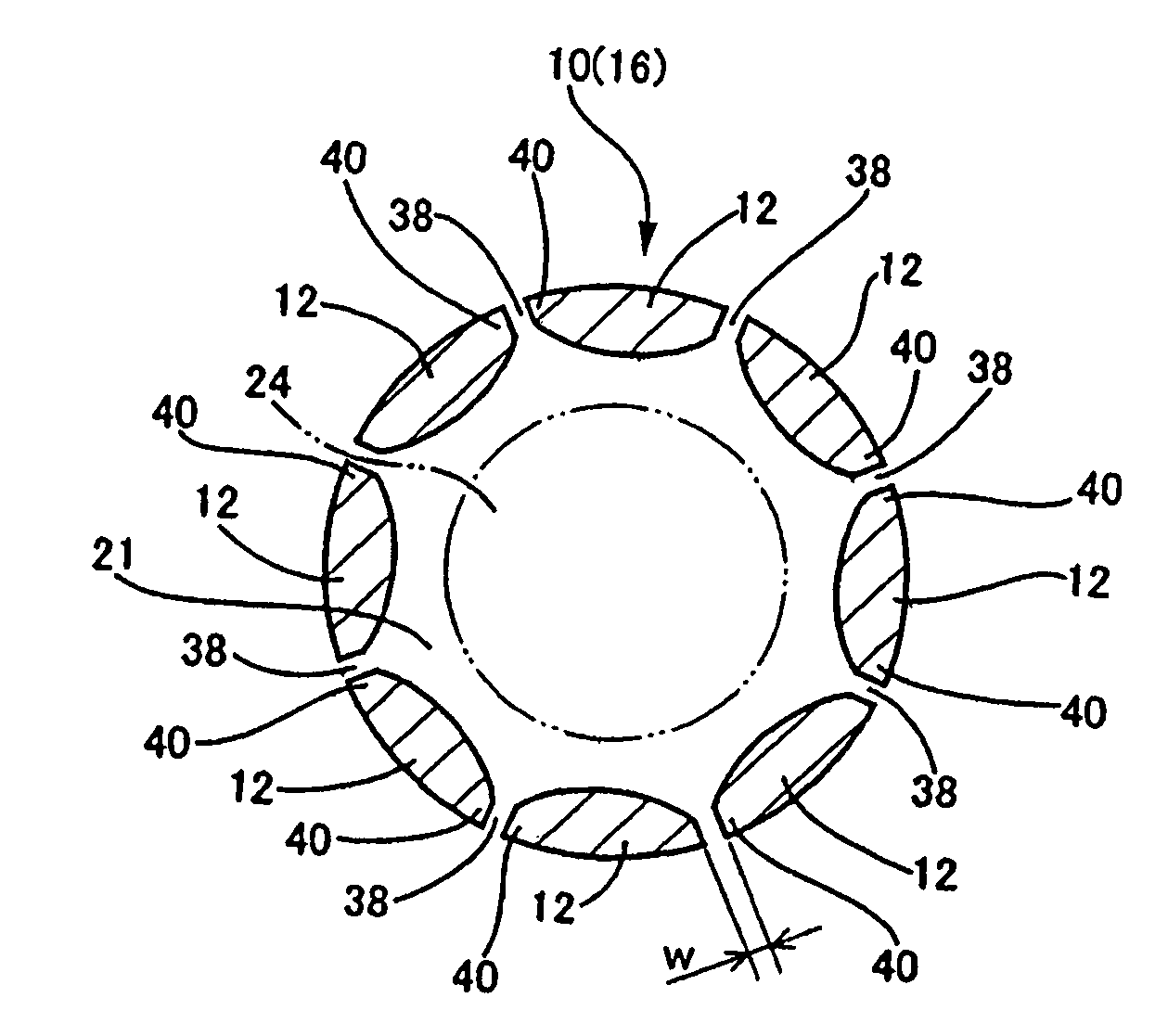
The present invention provides an improved structure for a catheter with a coil body that can be operated in a simpler manner without compromising the performance of the coil body in a procedure for dilating an occluded area in a blood vessel. The catheter has a distal portion with a larger channel for inserting a balloon catheter, which eliminates the need for a separate small balloon catheter. However, increasing the outer diameter of the coil body to achieve this larger channel creates new problems, such as reduced flexibility and increased rigidity at the distal portion. The present invention solves these problems by providing a catheter with a coil body that has a distal portion with a greater distance between coils, allowing for a larger channel without reducing the flexibility of the coil body. This results in a simpler and more flexible catheter that can be easily operated in blood vessels.

Problems solved by technology

In reality, however, the inventors found that increasing the outer diameter of the coil body would present numerous problems.
For this reason, increasing the outer diameter of the coil body generally reduces the flexibility of the entire coil body.
This gives rise to problems, such as the difficulty inserting the coil body smoothly into meandering blood vessels so as not to damage the interior walls of the blood vessels.
If a coil with a larger outer diameter is formed with thinner metal wires to prevent the aforementioned problems, the flexibility of the entire coil increases excessively.
As a result, torque transmissibility decreases significantly.

Method used


Image

  • Catheter and method of producing the same
  • Catheter and method of producing the same
  • Catheter and method of producing the same

Examples


Embodiment Construction

[0051]The present invention will be explained with respect to preferred embodiments. However, the preferred embodiments are not intended to limit the present invention, but include the following:

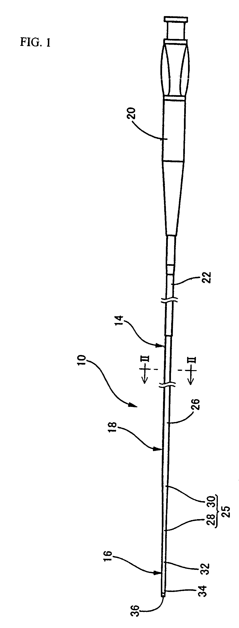
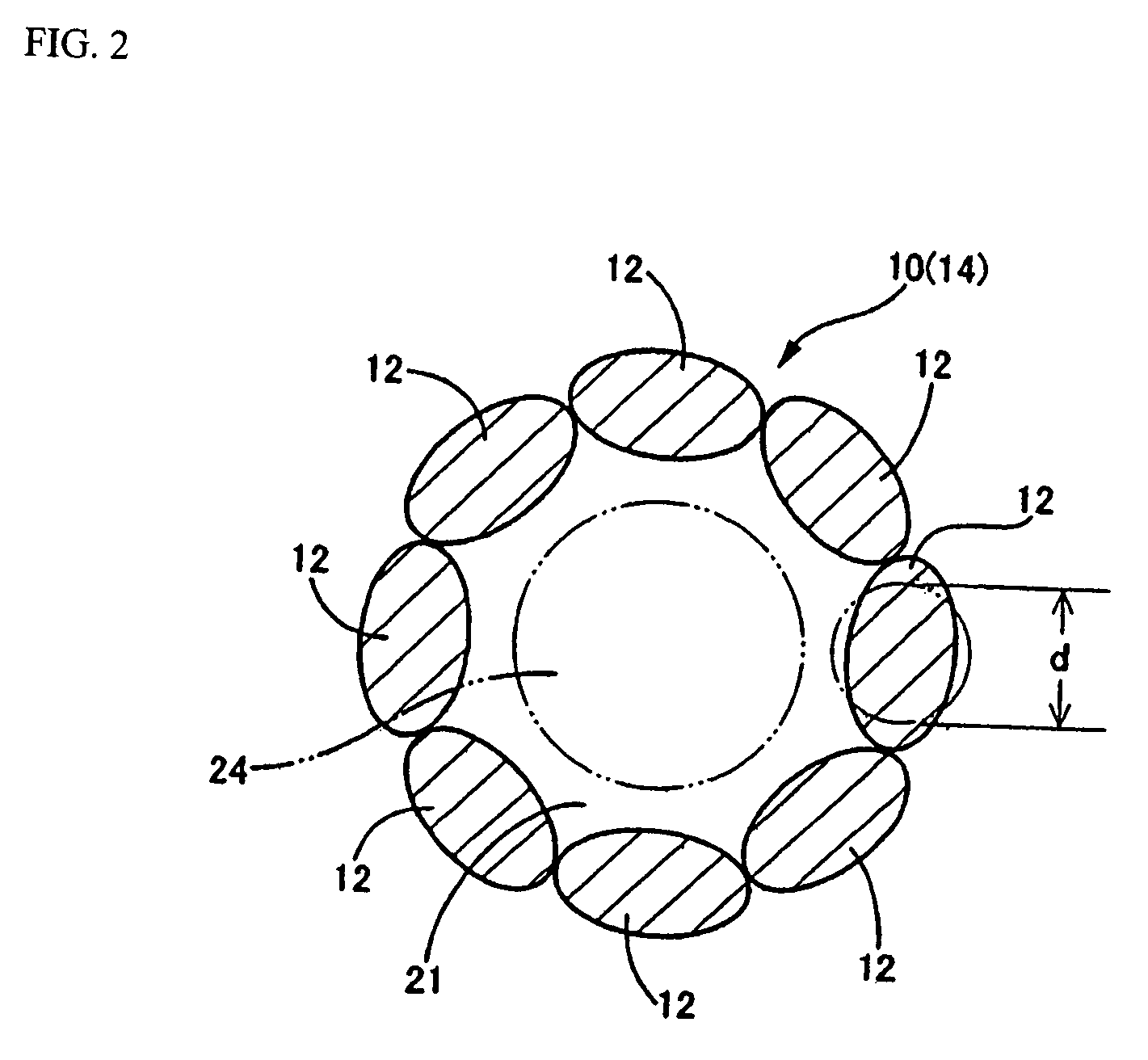
[0052] A catheter including a catheter body of a specified length to be inserted into the human body; wherein the catheter body comprises a coil body formed by winding or stranding metal wires and having a distal portion and a proximal portion; and wherein the pitch in the distal portion of the coil body is substantially or nearly the same as the pitch in the proximal portion, while the distance between each pair of the metal wires running adjacent to each other in the distal portion is larger than the distance between each pair of the metal wires running adjacent to each other in the proximal portion.

[0053] A catheter described in above, wherein the coil body is electro-polished in the distal portion in order to polish the surface of the metal wires in the distal portion and create a gap b...


PUM

PropertyMeasurementUnit
outer diametersaaaaaaaaaa
outer diameteraaaaaaaaaa

Abstract

A catheter body includes a coil body (10) which is formed by winding or stranding metal wires (12) and having a distal portion (16) and a proximal portion. The distance between coils (12) adjacent to each other in the distal portion (16) is greater than the distance between coils (12) adjacent to each other in the proximal portion (18 or 14). The pitch in the distal portion (16) of the coil body (10) is substantially or nearly the same as the pitch in the proximal portion (18 or 14).

Description

BACKGROUND OF THE INVENTION[0001]1. Field of the Invention[0002]The present invention relates to an improved catheter having a catheter body comprising a coil body, as well as a method of producing such catheter in a favorable manner.[0003]2. Description of the Related Art[0004]Catheters have been known as medical apparatuses that are used via insertion into blood vessels, gastrointestinal tracts, urinary tracts and other tubular organs and tissues of humans. As one type of these catheters, those having its main body, or part inserted into the human body, comprising a coil body formed by winding or stranding long, thin round metal wires are known (such as the one disclosed in Japanese Patent Laid-open Publication No. 2004-242973). For example, these catheters are favorably used in procedures that are performed to dilate an occluded area in a blood vessel.[0005]Specifically, when performing a procedure using one of these catheters having a coil body as the catheter body, generally a ...

Claims


Application Information

Patent Timeline
Patent Type & Authority Patents(United States)
IPC IPC(8): A61B5/00
CPCA61M25/0012A61M25/0043A61M2025/09191
Inventor SHIMOGAMI, MANABUGOTO, SHINICHINIHONMATSU, MASAAKI
Owner ASAHI INTECC CO LTD
Learn More