
Alignment of tape cartridge accessor

a tape cartridge and accessor technology, applied in the field of automatic tape library systems, can solve the problems of reducing system performance, affecting the accuracy of tape cartridge accessors, and increasing the complexity of tape cartridge accessors, and achieve the effect of maximizing storage capacity

Inactive Publication Date: 2011-03-15
INT BUSINESS MASCH CORP
View PDF41 Cites 0 Cited by
  • Summary
  • Abstract
  • Description
  • Claims
  • Application Information

AI Technical Summary

Benefits of technology

This solution enhances registration accuracy and reliability, reduces system costs, and eliminates the need for time-consuming recalibration by continuously verifying the picker's position and using tape cartridge cells as fiducials, maximizing storage capability and system performance.

Problems solved by technology

A problem with prior automated storage libraries designs which contributed to their relatively higher complexity and resultant higher costs relates to the multiplicity and complexity of various sensing mechanisms used to sense several parameters of the operating storage library.
Picker registration has proven to be a problem, resulting in occasional dropped cartridges and decreased system performance.
In practice this method has been less than perfect, with some systems suffering jams or drops.
However, the production cost of such a system is high.
However, registration accuracy has proven to be a problem because the environment is dynamic and the robot accessor (picker) begins to drift over time.
Accordingly, a cost-effective imaging system for aligning a picker in an automated tape library system has not been developed.

Method used


Image

  • Alignment of tape cartridge accessor
  • Alignment of tape cartridge accessor
  • Alignment of tape cartridge accessor

Examples


Embodiment Construction

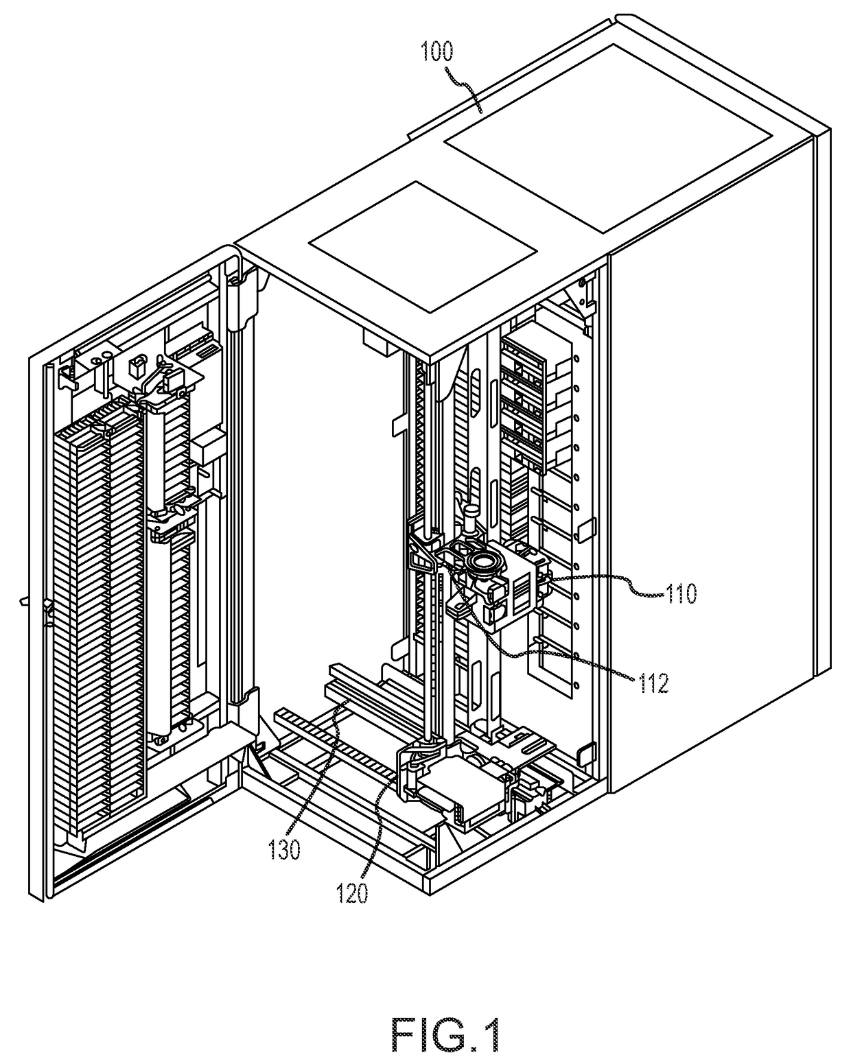
[0048]In the following description of the exemplary embodiment, reference is made to the accompanying drawings that form a part hereof, and in which is shown by way of illustration the specific embodiment in which the invention may be practiced. It is to be understood that other embodiments may be utilized as structural changes may be made without departing from the scope of the present invention.

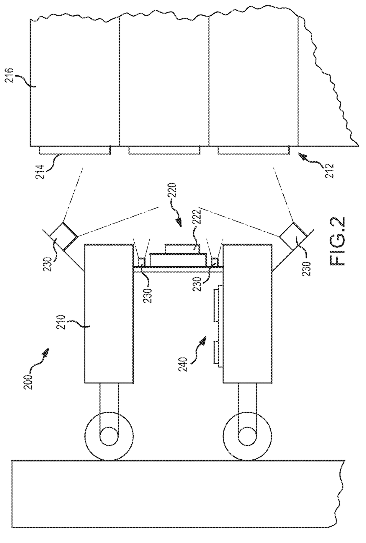
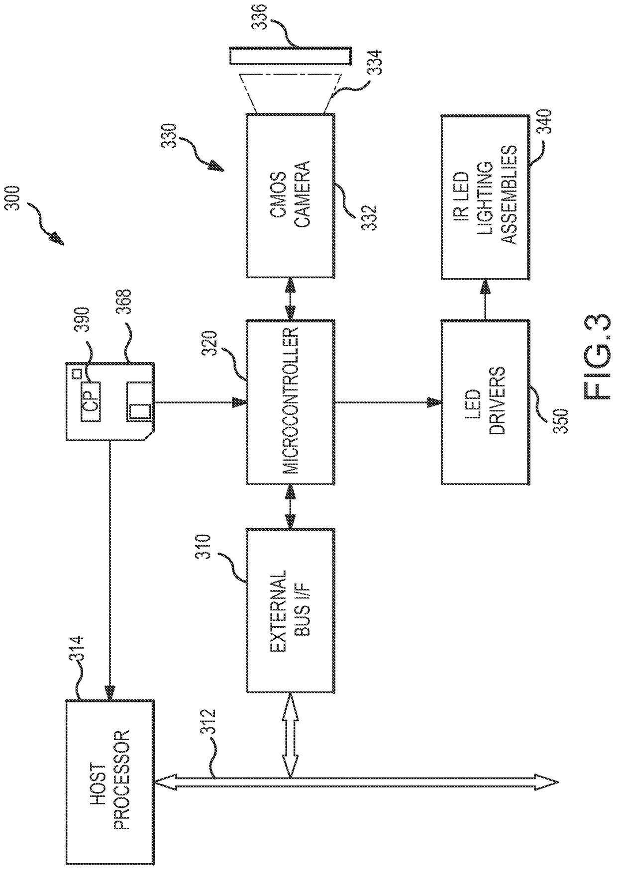
[0049]The present invention provides an image-based bar-code reading and robotic registration apparatus and method for use in automated tape library systems. The present invention positions an imager on a picker assembly with its own illumination source and appropriate optics to filter out ambient light. The imager connects to a microprocessor in its immediate vicinity. All image acquisition and processing are done by these components. To ensure operation independent of illumination variations, the image processing code developed for this invention automatically adapts to dynamic lighting s...


PUM


Abstract

A method for aligning a tape cartridge accessor with cartridges in cells of a tape cartridge magazine is provided. IR illumination is applied to an object expected to include a desired physical feature. Specular reflections are received from the illuminated object to create an image of the object. Dynamic image thresholding is applied to the image to select an optimum gray scale level of the image expected to include the desired physical feature. Bounding boxes are used to identify the location of the desired physical feature in the thresholded image.

Description

CROSS-REFERENCE TO RELATED APPLICATION[0001]This application is a division of U.S. application Ser. No. 09 / 957,948, filed Sep. 20, 2001, which is incorporated herein by reference.BACKGROUND OF THE INVENTION[0002]1. Field of the Invention[0003]This invention relates in general to automated tape library systems, and more particularly to an image based bar code reading and robotic registration apparatus and method for use in automated tape library systems.[0004]2. Description of Related Art[0005]Magnetic tape has long been used as a storage media for audio, video and computer information. Tape cartridges have been used extensively because they provide a convenient way to house and support a length of magnetic tape for engagement by a transducer in a tape drive while protecting the tape upon removal of the cartridge.[0006]Storage libraries provide large capacity secondary storage to modern computing requirements. Such storage libraries typically employ robotic control mechanisms used by...

Claims


Application Information

Patent Timeline
Patent Type & Authority Patents(United States)
IPC IPC(8): G06K9/36G06F7/00G06K7/10
CPCG06K7/10732
Inventor CHAMBERLAIN, LYLE JOSEPH
Owner INT BUSINESS MASCH CORP
Learn More