
Single chain linear actuator

a linear actuator and single chain technology, applied in the direction of chain elements, gearing, hoisting equipment, etc., can solve the problems of telescopic hydraulic jacks that do not have particularly/or oil, and the linear actuator typically has a poor side load stiffness and/or oil, etc., to achieve good side load stiffness, good axial stiffness, and extended length

Active Publication Date: 2011-03-15
MARINE CANADA ACQUISITIONS INC
View PDF16 Cites 16 Cited by
  • Summary
  • Abstract
  • Description
  • Claims
  • Application Information

AI Technical Summary

Benefits of technology

"The present invention provides a linear actuator with a helically winding chain that does not require a planar chain track or path within the actuator housing. This allows for a linear actuator that does not require oil and has a large extended length to retracted length ratio, good axial stiffness, and good side load stiffness. The actuator includes a chain with adjacent first and second links, a pivotal connection pivotally connecting the first link to the second link, and a locking mechanism releasably locking the first link and the second link to prevent the first link from pivoting about the pivot axis. The actuator can move between an extended position and a retracted position, and at least a portion of the chain is helically wound when the chain is in the retracted position."

Problems solved by technology

However, these linear actuators typically have a poor side load stiffness and / or require oil.
For example, telescoping hydraulic jacks do not have particularly good side load stiffness and require oil.
Accordingly, telescoping hydraulic jacks cannot be used in applications which require a good side load carrying capacity or where the use oil is not permissible.
However, they do not have a large extended length to retracted length ratio because a planar chain track, or chain path, is required within the actuator housing to guide the chain as it is being displaced.

Method used


Image

  • Single chain linear actuator
  • Single chain linear actuator
  • Single chain linear actuator

Examples


Embodiment Construction

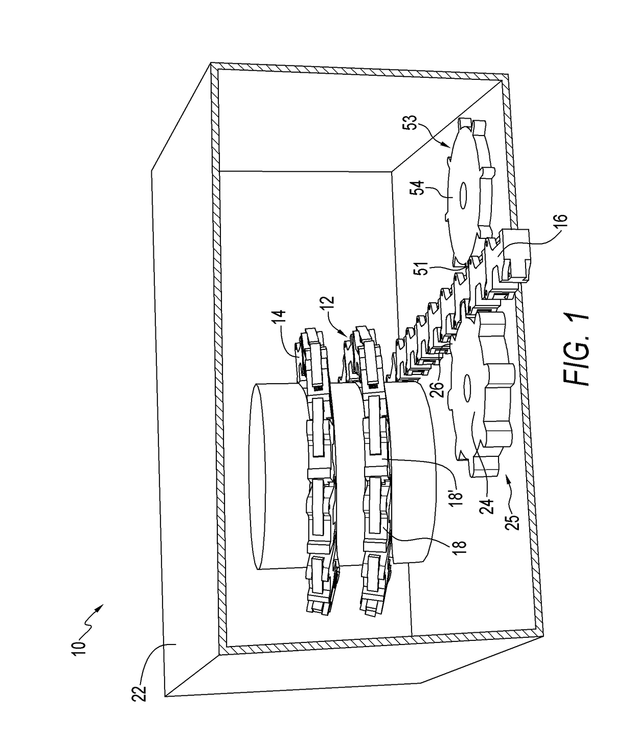
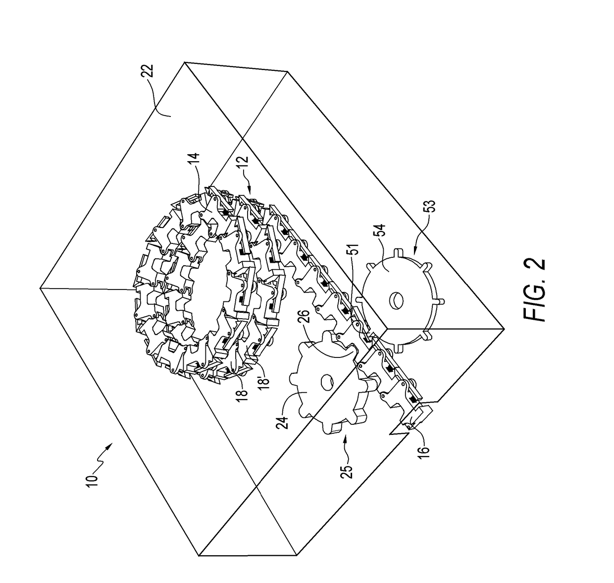
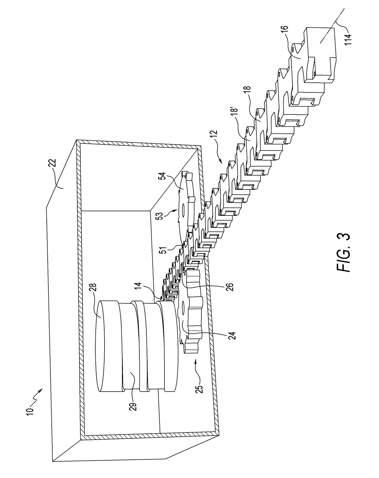
[0019]Referring to the drawings, and first to FIG. 1, this shows a single chain linear actuator 10. The linear actuator 10 comprises a helically winding chain 12 which is reciprocatingly received in an actuator housing 22. The chain 12 has a proximal end link 14, a distal end link 16, and a plurality of inter-connected links 18 therebetween. The chain 12 is movable between a retracted position shown in FIGS. 1 and 2, and an extended position shown in FIG. 3.

[0020]Referring now to FIG. 4, a first one of the inter-connected links 18 is shown in greater detail. The link 18 has a first end 30, a second end 32, and a longitudinal axis 100. There is a clevis 34 at the first end 30 of the link 18. The clevis 34 has opposed inner mating surfaces. In FIG. 4 only one of the mating surfaces 37 is shown. The inner mating surfaces are angularly tilted relative to the first end 30 of the link 18. There is a mating portion 35 near the second end 32 of the link 18. The mating portion 35 is angularl...


PUM


Abstract

A linear actuator comprises a chain having adjacent first and second links. A pivotal connection pivotally connects the first link to the second link. The first link is pivotable about a pivot axis which is non-perpendicular to a longitudinal axis of the first link. A locking mechanism releasably locks the first link and the second link to prevent the first link from pivoting about the pivot axis. A releasing mechanism releases the locking mechanism to allow the first link to pivot about the pivot axis. A drive mechanism moves the chain between an extended position and a retracted position. At least a portion of the chain is helically wound when the chain is in the retracted position.

Description

CROSS REFERENCE TO RELATED APPLICATION[0001]This application claims the benefit of provisional application 60 / 890,688 filed in the United States Patent and Trademark Office on Feb. 20, 2007, the disclosure of which is incorporated herein by reference and priority to which is claimed.BACKGROUND OF THE INVENTION[0002]The present invention relates to a single chain linear actuator and, in particular, to a single chain linear actuator having helically winding chains.[0003]One measure of a linear actuator is the ratio of extended length to retracted length. For most linear actuators this ratio is 1.8 to 1. Although, there are linear actuators, such as scissor lifts and telescoping hydraulic jacks, in which the ratio of extended length to retracted length exceeds 3 to 1. This allows such linear actuators to provide a relatively large amount of movement while being positioned in a relatively small space. However, these linear actuators typically have a poor side load stiffness and / or requi...

Claims


Application Information

Patent Timeline
Patent Type & Authority Patents(United States)
IPC IPC(8): F16H27/02
CPCB66D1/54F16G13/20Y10T74/18832Y10T74/1884
Inventor SCOTT, JONFETCHKO, ERIC
Owner MARINE CANADA ACQUISITIONS INC
Learn More