
Tool for removing intraocular foreign bodies

a technology for removing foreign objects and tools, applied in the field of surgical tools, can solve the problems of limited forceps, difficult to capture irregular shapes of objects using forceps-type tools, and small bite size to remove relatively large foreign objects, etc., and achieve the effect of low friction coefficien

Inactive Publication Date: 2011-02-22
UNIV OF SOUTH FLORIDA
View PDF3 Cites 47 Cited by
  • Summary
  • Abstract
  • Description
  • Claims
  • Application Information

AI Technical Summary

Benefits of technology

[0009]One drawback of the earlier device is that it is difficult to manufacture a flexible, cinchable basket. Still, the highly novel concept of a basket, as distinguished from the jaws of a forceps, has many advantages. The diameter of the basket, for example, may be up to 6 mm, thereby enabling the removal of objects larger than any object retrievable by a conventional forceps. Moreover, objects having irregular shapes and objects having smooth, low coefficient of friction or non-magnetic surfaces are capturable by a basket.
[0010]What is needed, then, is a tool for removing intraocular foreign bodies that incorporates a basket that is not difficult to manufacture so that the benefits of a basket-based tool may be economically realized.

Problems solved by technology

Forceps are limited in that the “bite size” may be too small to remove relatively large foreign objects.
Moreover, an object having an irregular shape is often hard to capture using a forceps-type tool.
A smooth (low coefficient of friction), non-magnetic object like smooth glass or a BB is also hard to capture using a forceps.
One drawback of the earlier device is that it is difficult to manufacture a flexible, cinchable basket.

Method used


Image

  • Tool for removing intraocular foreign bodies
  • Tool for removing intraocular foreign bodies
  • Tool for removing intraocular foreign bodies

Examples


Embodiment Construction

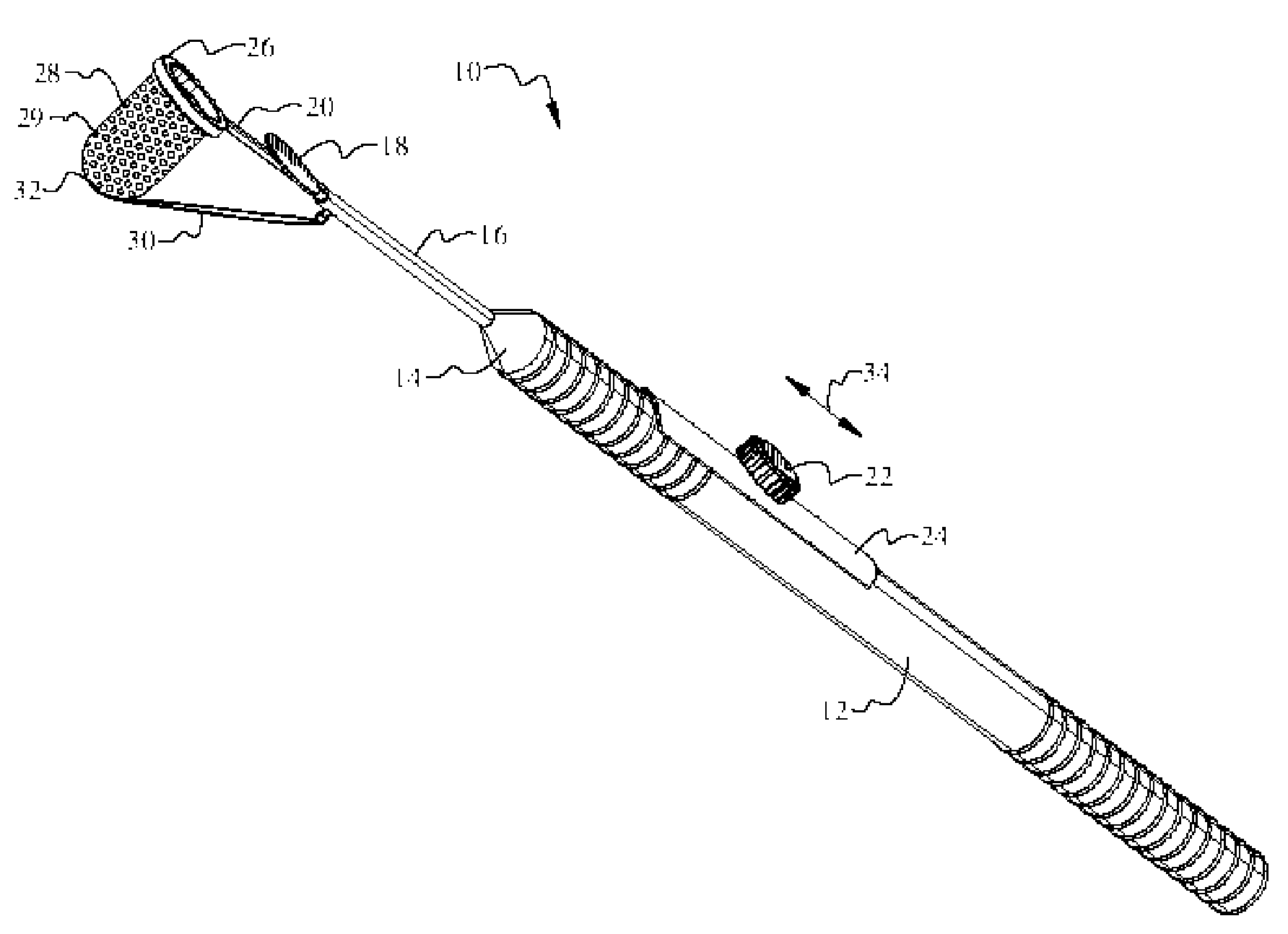
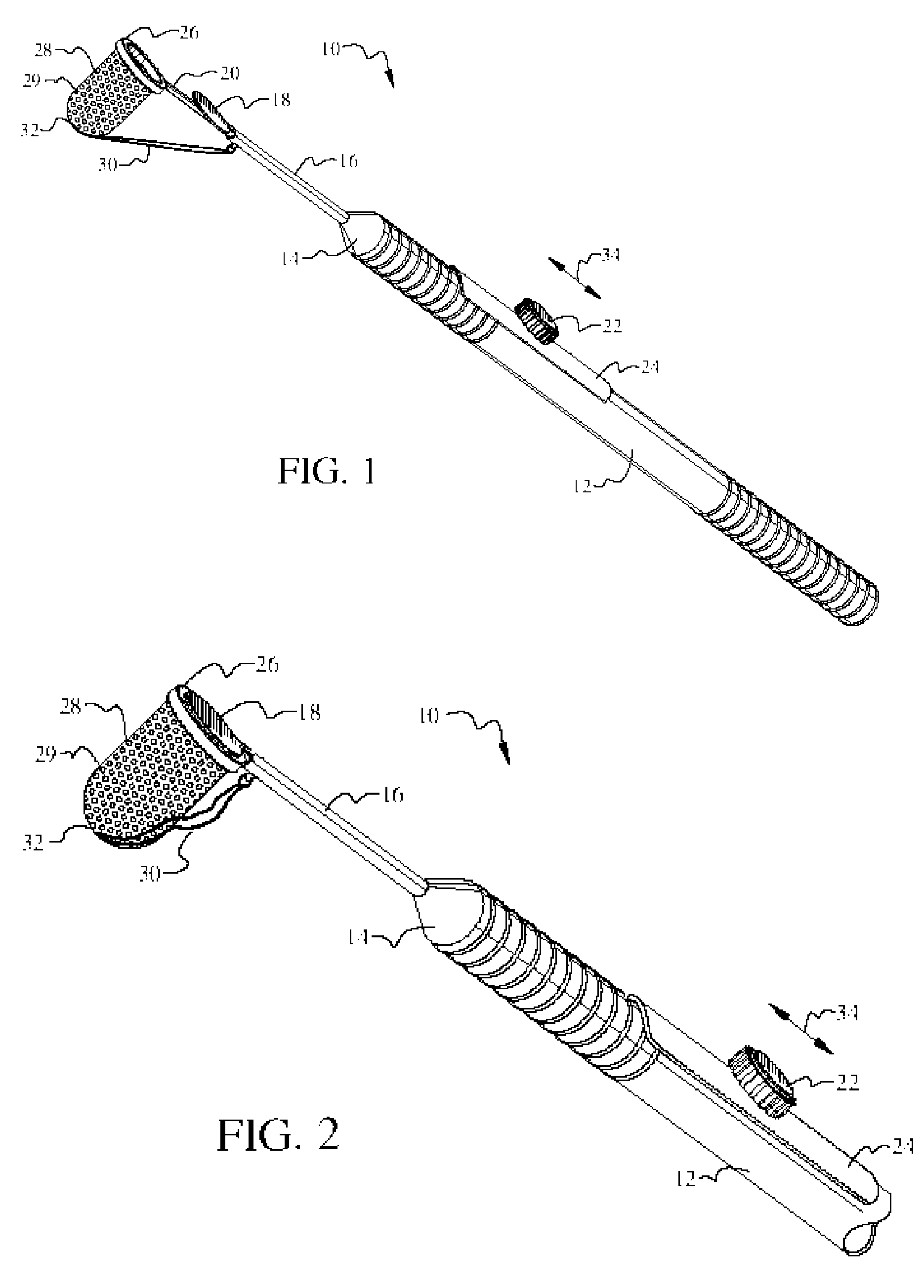
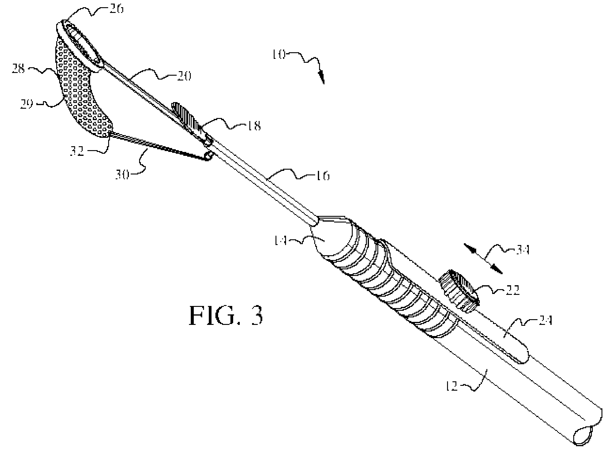
[0028]Referring now to FIGS. 1-3, it will there be seen that an illustrative embodiment of the invention is denoted as a whole by the reference numeral 10.

[0029]Novel intraocular foreign body extractor 10 includes elongate base 12 that is sized for comfortable holding in a human hand. Base 12 is cylindrical along its extent but its leading 14 is frusto-conical in configuration, i.e., said leading end tapers downwardly in diameter from the diameter of the cylindrical base to the diameter of hollow rod 16.

[0030]A flat, circular, basket closure means or lid 18 is formed integrally with hollow rod 16 at the distal free end thereof. Rod 16 and hence lid 18 have a fixed position and are not movable relative to base 12.

[0031]Hollow rod 16 has a lumen that slideably receives elongate control rod 20 therein. The proximal end of elongate control rod 20 is disposed within the interior of base 12 and is mechanically connected by any suitable means to control knob 22. An elongate slot formed in ...


PUM


Abstract

A medical instrument captures and removes very large intraocular foreign bodies. The foreign bodies may have an irregular shape, a low coefficient of friction, and be made of non-magnetic materials. A fixed position hollow rod is mounted to a leading end of an elongate base and a lid is mounted to the distal end of the hollow rod. A control rod is slideably received within the hollow rod and a control knob slideably mounted on the elongate base is connected to the control rod to control extension and retraction of the control rod. A silicone basket depends from a rim formed at the distal end of the control rod. A silicone wire interconnects the hollow rod and a bottom of the basket so that the basket is drawn parallel to the control rod when the control rod is extended. The lid covers the basket when the control rod is retracted.

Description

CROSS-REFERENCE TO RELATED DISCLOSURES[0001]This disclosure is a continuation-in-part of an earlier disclosure of the same title filed on Sep. 2, 2004, Ser. No. 10 / 711,226, which earlier disclosure claims priority from U.S. provisional application Ser. No. 60 / 481,322, entitled: “Intraocular Foreign Body Basket,” filed Sep. 2, 2003. Both of said earlier disclosures are hereby incorporated into this disclosure by reference.BACKGROUND OF THE INVENTION[0002]1. Field of the Invention[0003]This invention relates, generally, to surgical tools. More particularly, it relates to a surgical tool used by retina specialists for extracting intraocular foreign bodies.[0004]2. Description of the Prior Art[0005]The foreign body extractors in common use typically include opposed jaws that operate as forceps. A well-known tool, known as a vitreoretinal forceps, has a stainless steel construction, a serrated plastic handle, and is autoclavable. The jaws may be smooth or serrated, and they may open hori...

Claims


Application Information

Patent Timeline
Patent Type & Authority Patents(United States)
IPC IPC(8): A61B17/50
CPCA61B17/221A61F9/00709A61B2017/00287
Inventor GOLDSTEIN, BURTON G
Owner UNIV OF SOUTH FLORIDA
Learn More