
Solar tracker

a tracker and solar energy technology, applied in the safety of solar heat collectors, pv power plants, lighting and heating apparatus, etc., can solve the problems of no storage means, high cost of geared motors, and added cost of producing trackers

Inactive Publication Date: 2011-02-08
SOLARRESERVE TECH
View PDF24 Cites 45 Cited by
  • Summary
  • Abstract
  • Description
  • Claims
  • Application Information

AI Technical Summary

Benefits of technology

"The patent describes a solar tracker that can withstand extreme weather conditions. It includes a solar array, a frame, a base, a pivot frame, and two actuators. The solar array is mounted on the frame and captures sunlight. The pivot frame is connected to the frame and allows the solar array to move in the azimuthal direction (north-south direction). The base is also connected to the pivot frame and allows the solar array to move in the elevational direction (up-down direction). The two actuators control the movement of the solar array in the azimuthal and elevational directions, respectively. The solar tracker can be raised and stowed. The technical effect of this patent is to provide a reliable and durable solar tracker that can withstand extreme weather conditions and efficiently track the sun's movement."

Problems solved by technology

However, geared motors can be expensive and add to the cost of producing the tracker.
One problem with current tracker systems is that they are designed to mount on a post and have no means of stowing in extreme winds.
Thus, the wind load resistance of the tracker system is low and can result in damage to the tracker or to the solar panels during extreme winds.
Additionally, because current tracker systems are designed to mount on a post, all of the loading is transferred to the base of the post, hindering the ability to integrate the solar tracker onto a building structure.

Method used


Image

  • Solar tracker
  • Solar tracker
  • Solar tracker

Examples


first embodiment

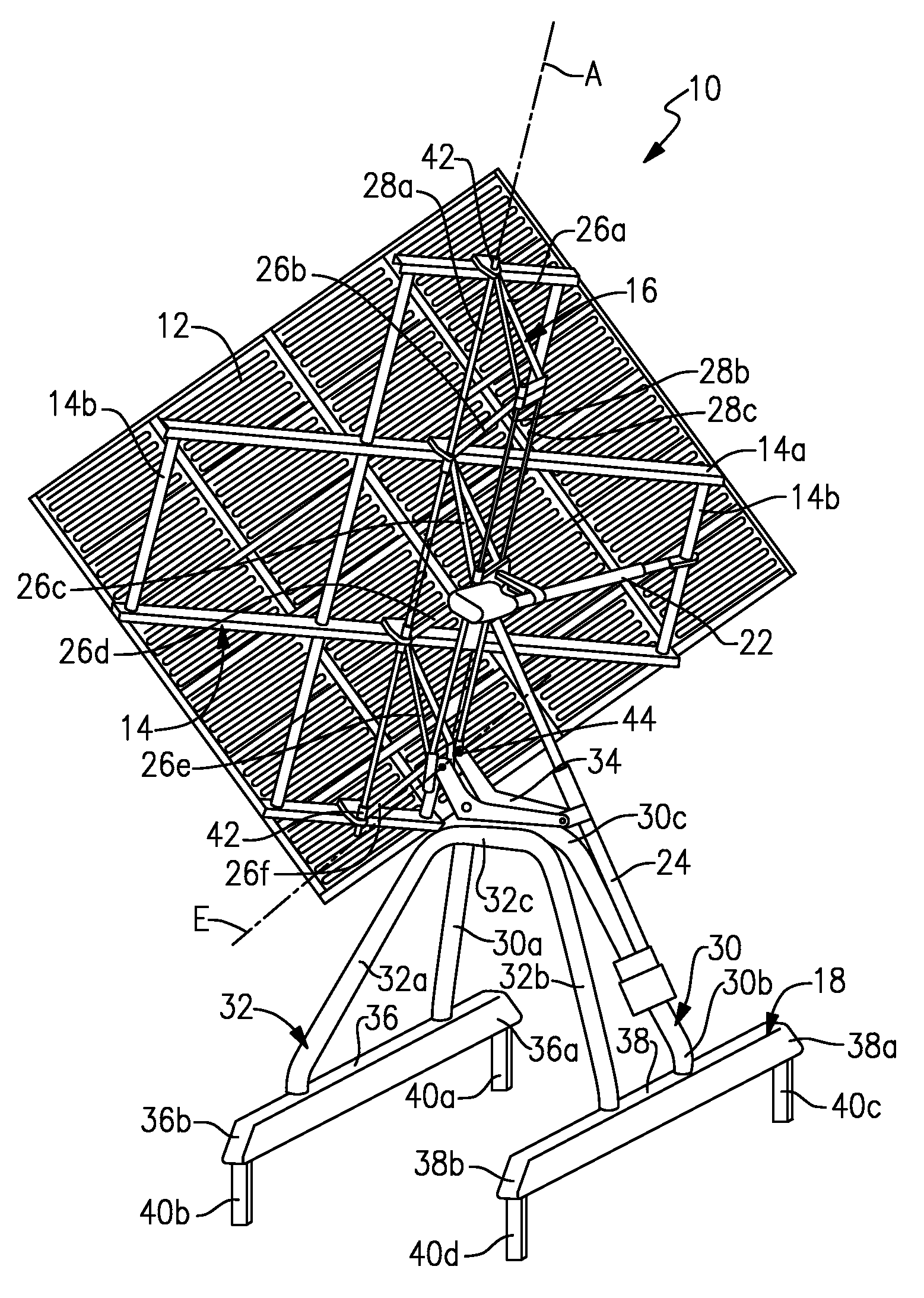
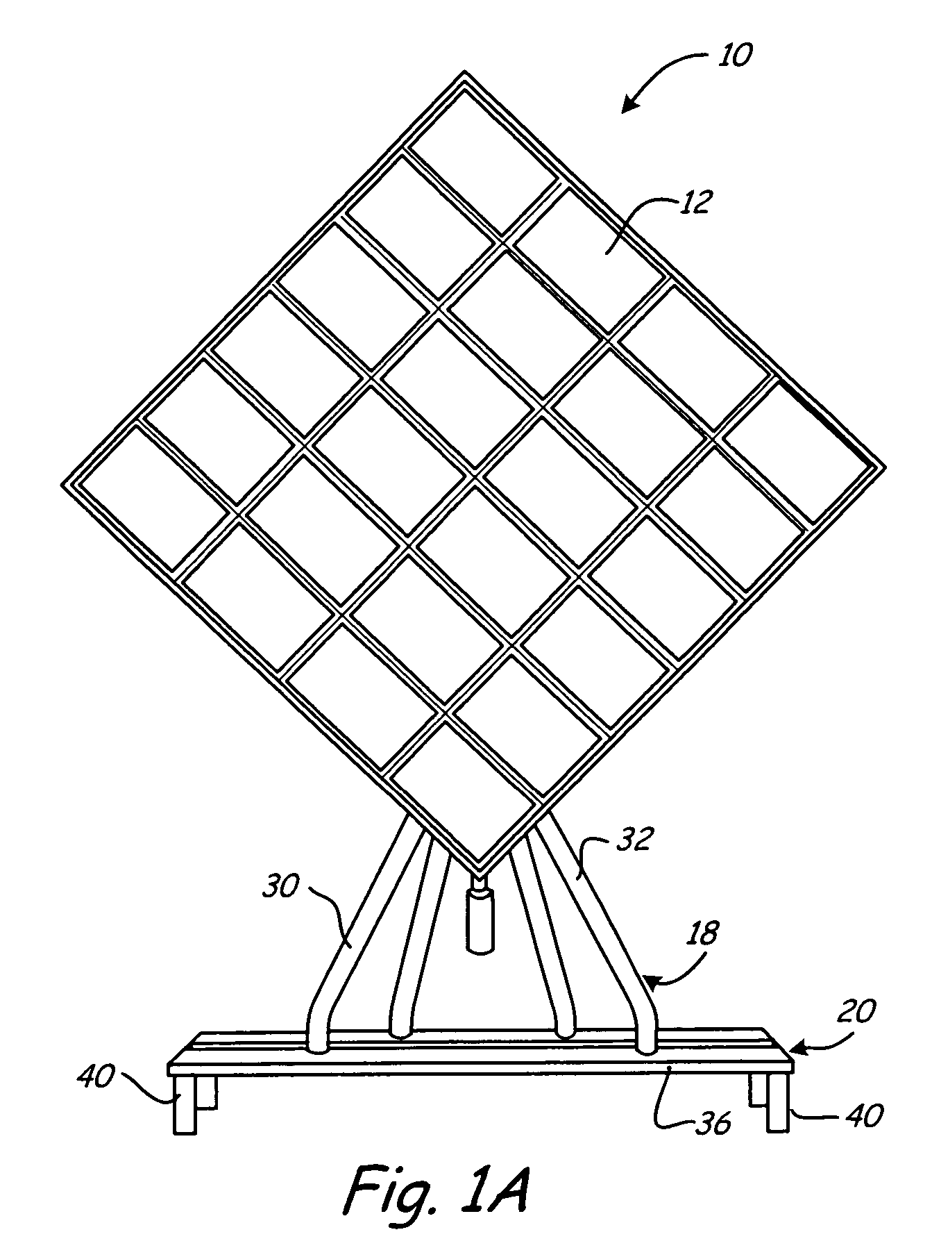
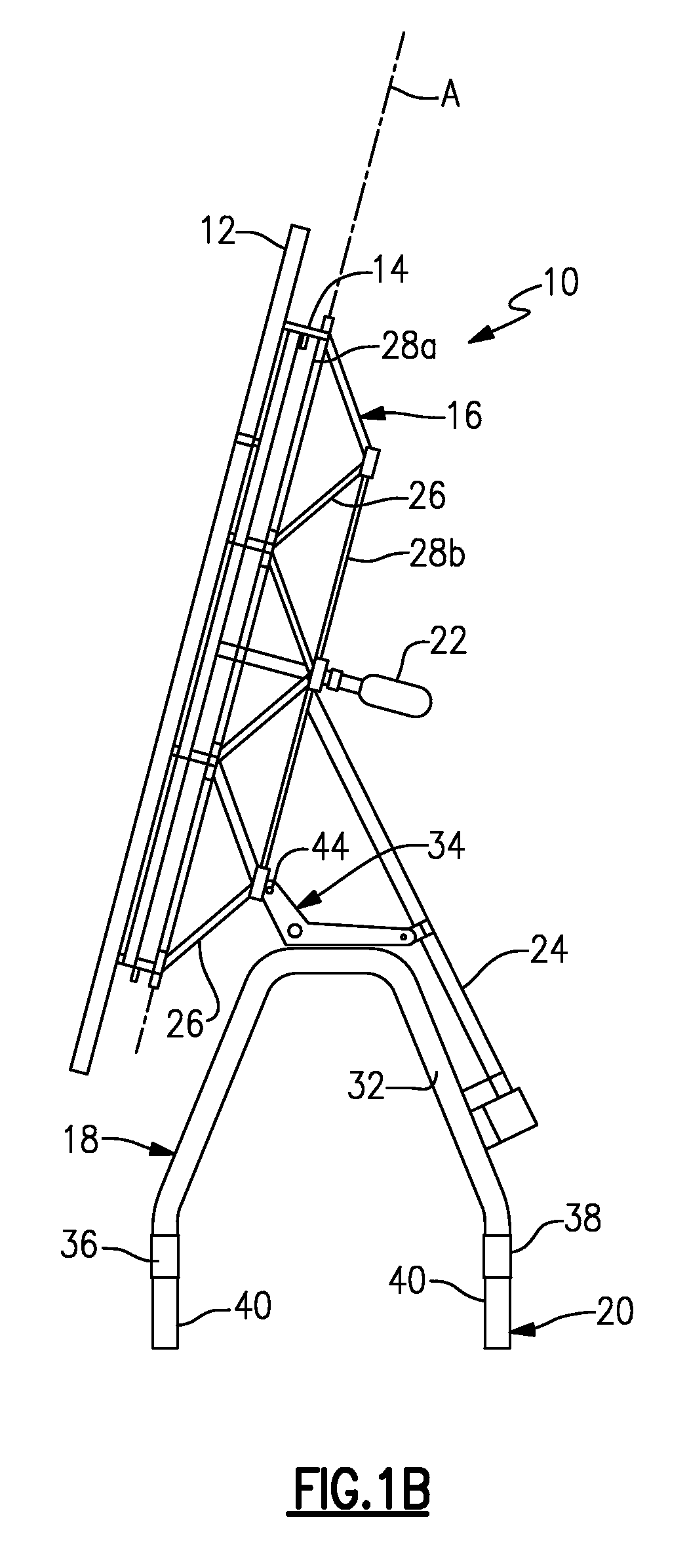
[0015]FIGS. 1A and 1B show a front view and a side view, respectively, of two-axis solar tracker 10 in a raised position and will be discussed in conjunction with one another. Solar tracker 10 generally includes solar array 12 consisting of multiple panels, frame 14, truss 16, base 18, leg mount 20, first actuator 22, and second actuator 24. Truss 16 is a stiff, lightweight, and cost-effective support for solar array 12 and is pivotable relative to frame 14 and base 18. In order to protect solar array 12 during extreme weather conditions, solar tracker 10 is pivotable between a raised position and a stowed position. Solar tracker 10 with truss 16 has increased wind load resistance and is adaptable to various building structures while using conventional linear actuators.

[0016]Solar tracker 10 is designed to align solar array 12 with respect to the sun so that it collects the maximum amount of solar energy. Solar energy is absorbed into solar array 12 where it is subsequently converte...

second embodiment

[0032]FIG. 7 shows a perspective view of solar tracker 100 in a raised position. Solar tracker 100 generally includes solar array 102, frame 104, first linkage arm 106, second linkage arm 108, first actuator 110, second actuator 112, and leg mounts 114a-114d. Linkage arms 106, 108 of solar tracker 100 allow solar array 102 to be moved into a stowed position during high winds. Solar array 102 of solar tracker 100 functions in the same manner as solar array 12 of solar tracker 10. Similar to solar tracker 10, solar tracker 100 is also pivotable between a raised position and a stowed position, uses conventional linear actuators, and is adaptable to various building structures.

[0033]Frame 104 is attached to solar array 102 and connects solar array 102 to first and second linkage arms 106, 108. Frame 104 generally includes horizontal crossbars 104a and 104b and pivot frame 116. Pivot frame 116 has a first end 116a and a second end 116b. First end 116a of pivot frame 116 is connected to c...


PUM


Abstract

A two-axis solar tracker is capable of withstanding extreme weather conditions. The solar tracker includes a solar array, a frame, a base, a pivot frame, and a first and second actuator. The solar array is mounted to the frame and captures sunlight. The base is pivotally connected to the frame and defines a pivot axis for elevational movement of the solar array. The pivot frame is also pivotally connected to the frame and defines a pivot axis for azimuthal movement of the solar array. The first actuator controls elevational movement of the solar array and the second actuator controls azimuthal movement of the solar array. The solar tracker is pivotable between a raised position and a stowed position.

Description

BACKGROUND OF THE INVENTION[0001]Solar cells, or photovoltaic cells, have the ability to convert sunlight directly into electricity. In order to capture the maximum amount of sunlight during the day, a tracker is connected to the cells and continuously aligns the light-absorbing panels of the cells in a direction perpendicular to rays from the sun so that the cells can absorb the highest amount of energy from the rays of sunlight. This is particularly important for high performance solar panels having concentrated cells. Current trackers are typically dual axis tracking systems having a linear actuator for elevational control and a geared or linear motor for azimuthal control. However, geared motors can be expensive and add to the cost of producing the tracker.[0002]One problem with current tracker systems is that they are designed to mount on a post and have no means of stowing in extreme winds. Thus, the wind load resistance of the tracker system is low and can result in damage to...

Claims


Application Information

Patent Timeline
Patent Type & Authority Patents(United States)
IPC IPC(8): H01L31/045F24S50/20H02S30/20
CPCF24J2/5424H02S20/00F24J2/4638Y02E10/50Y02E10/47H02S20/32H02S20/23F24S30/455F24S40/85Y02B10/10
Inventor DOLD, ROBERT H.NIETER, JEFFREY J.
Owner SOLARRESERVE TECH
Learn More