Apparatus and use of the apparatus for the determination of the density of a plasma

a technology of apparatus and density, applied in the direction of instruments, specific gravity using flow properties, measurement devices, etc., can solve the problems of difficult determination of electron density, small investment and maintenance requirements, and few industry-compatible products, and achieve high accuracy and robust measurement methods.

Active Publication Date: 2011-02-01
BRINKMANN RALF PETER
View PDF12 Cites 4 Cited by
  • Summary
  • Abstract
  • Description
  • Claims
  • Application Information

AI Technical Summary

Benefits of technology

[0026]The probe design according to the invention has a number of fundamental advantages. By using a suitable design of the insulating areas, and by varying the ratio of sheath diameter to core diameter, the composition of the entire characteristic of individual multipole terms can be changed over a wide range. For example, all terms except for the dipole contribution can be eliminated. In this way, a holder used to feed the signal, in particular a high-frequency signal, to the probe can be placed in a high-frequency-free region so as not to perturb the measurement. Elimination of the monopole contribution also eliminates coupling to the wall.
[0027]In principle, the signal can also be coupled in by optical means, for example using a glass fiber, rather than via a holder with an electrical cable. This could even further reduce the electrical interference with the plasma. The optical signals can be transformed into electrical signals by an autonomous electronic circuit disposed in the probe, which then would also have to retransmit the measurement results (e.g., optically) to an evaluation unit.
[0032]The relatively simple and—in particular—unambiguous evaluation rule tailored for the corresponding elliptical and, more particularly, spherical shape of the probe allows the determination of the local plasma density with high accuracy.
[0033]The measurement method is very robust, particularly against the influence of reactive plasmas, without causing contamination of the plasma. The device according to the invention and the probe of the device can be manufactured a cost-effectively and thus especially industry-compatible.

Problems solved by technology

However, in technological plasmas, particularly in reactive plasmas, the determination of the electron density is difficult.
Of these methods, however, only a few are industry-compatible.
Their requirements on investment and maintenance are very small.
A disadvantage of plasma resonance spectroscopy is that a mathematical model is required to evaluate of measurement (i.e., to calculate the electron density from the resonance curve).
The evaluation of the signal, however, is problematic: It is difficult to deduce the really interesting quantity, the electron density of the plasma, from the measured primary signal (the frequency curve of the absorption).
The schematic electrical circuit diagram demonstrates the disadvantages of the previous method according to Sugai et al.
Practically, it is not possible to determine the corresponding resonance circuit parameters from the primary measurement curve (which has only limited accuracy).Even if the parameters were determinable, it would be impossible in practice to determine the actual plasma density: Although the parameters could be calculated for a given density with considerable effort, but this would not solve the “inverse problem” in a measurement.In the resonance characteristics, the coupling between the electrodes is superimposed on the coupling to the distant wall.
A spatial resolution of the measurement thus becomes impossible.
The method is therefore only suitable for asymmetric HF discharges.
Thus, the method does not allow for spatial resolution.

Method used


Image

  • Apparatus and use of the apparatus for the determination of the density of a plasma
  • Apparatus and use of the apparatus for the determination of the density of a plasma
  • Apparatus and use of the apparatus for the determination of the density of a plasma

Examples


Embodiment Construction

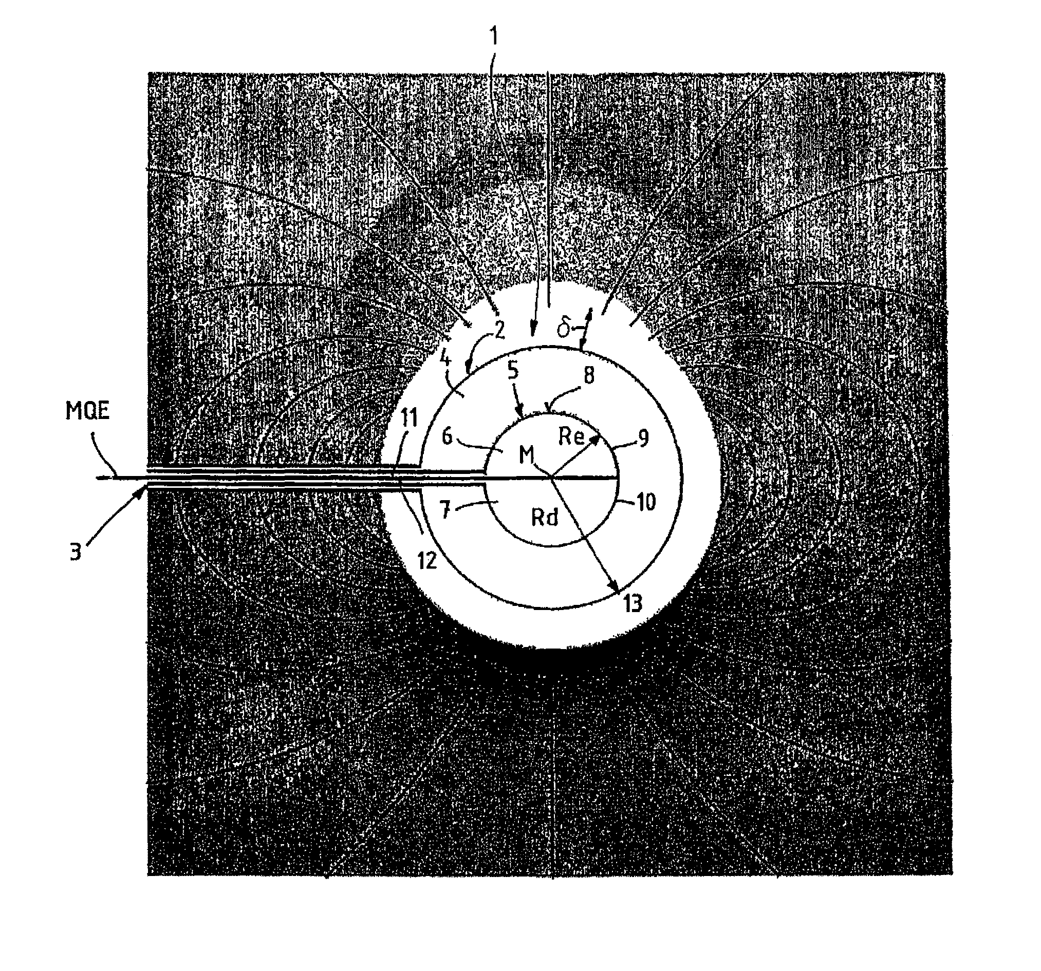
[0046]FIG. 1 shows the probe 1 as part of a device (not shown in detail) for measuring the electron density of a plasma. The probe 1 includes a spherical probe head 2 connected to a slim handle 3. FIG. 1 shows the configuration of probe 1 in a purely schematically drawing to illustrate the concept of the invention. All dimensions of FIG. 1 are chosen arbitrarily and are only meant to illustrate the concept of the invention.

[0047]The core of the probe 1 is the probe head 2 which consists of two shells. An outer sheath 4 of constant wall thickness surrounds a spherical probe core 5. The radii of the probe core and the sheath are denoted with Re und Rd, respectively. The probe core 5 includes two electrodes 6, 7, which are arranged symmetrically with respect to a plane MQE extending through the center M of the probe core 5, so that the surface 8 of the probe core 5 has electrode areas 9, 10 of opposite polarity. The electrodes 6, 7 are connected via the lines 11, 12 to a high-frequency...


PUM

PropertyMeasurementUnit
densityaaaaaaaaaa
polarityaaaaaaaaaa
resonance frequencyaaaaaaaaaa

Abstract

Device for determining the density of a plasma, with of a probe (1) which can be immersed into the plasma, with a probe head (2) in form of a three-axis ellipsoid, and a handle (3) connected to the probe head (2), wherein the probe head (2) has a sheath (4) and a probe core (5, 5a) surrounded by the sheath (4), wherein the surface (8) of the probe core (5, 5a) has electrode areas (9, 10) of opposite polarity which are insulated from each other. The probe core consists of electrodes (6, 7), to which a signal is applied. The absorption of that signal is measured and evaluated as a function of the frequency. Based on a multipole expansion, a mathematical model is constructed with which the absorption spectrum of the probe can be unambiguously evaluated. For a particular design of the probe, the response can be restricted to a single resonance, from which the electron density of the plasma (to be inferred from the resonance frequency) can be found by an unambiguous evaluation algorithm.

Description

BACKGROUND OF THE INVENTION[0001]The invention applies to a device and the use of such a device for the determination of the density of a plasma.[0002]Plasmas—electrically activated gases—find use in a variety of technical fields; their particular physical properties are frequently the basis of innovative products and processes. The exact supervision and—in the case of deviations—the adjustment of the plasma state are essential for the success of processes which are based on the use of technical plasmas. An important parameter of plasmas is the space and time dependent electron density ne. To know its value is essential for the characterization of plasmas. However, in technological plasmas, particularly in reactive plasmas, the determination of the electron density is difficult.[0003]The determination of the plasma density (and of other plasma parameters) is subject of a scientific discipline of its own, plasma diagnostics. A number of diagnostic methods have already been developed ...

Claims


Application Information

Patent Timeline
Patent Type & Authority Patents(United States)
IPC IPC(8): G01N9/32
CPCH05H1/0037
Inventor BRINKMANN, RALF-PETER
Owner BRINKMANN RALF PETER
Why Eureka
Try Eureka