
Predicting chronic optimal A-V intervals for biventricular pacing via observed inter-atrial delay

a technology of inter-atrial delay and optimal a-v interval, which is applied in the field of optimal programming of biventricular implantable pulse generators, can solve the problems of increasing the cost of chf treatment, increasing the difficulty of optimization studies, and increasing the difficulty of predicting optimal a-v intervals for biventricular filling

Active Publication Date: 2011-01-25
MEDTRONIC INC
View PDF15 Cites 26 Cited by
  • Summary
  • Abstract
  • Description
  • Claims
  • Application Information

AI Technical Summary

Benefits of technology

The patent text describes methods for optimizing the timing between atrial and ventricular contractions in patients who have received cardiac resynchronization therapy (CRT). These methods are based on techniques used for dual-chamber pacemakers. The goal is to maximize the filling of the left ventricle and ensure optimal contraction through the Frank-Starling mechanism. The main factor affecting the timing is the time required for electrical activity to pass through the inter-atrial conduction time (IACT) from the right atrium to the left atrium. The optimal timing is determined based on the start of electrical activity in the left atrium and the duration of the left atrial contraction. The patent suggests that by adjusting the timing between atrial and ventricular contractions, CRT devices can improve cardiac function and patient outcomes.

Problems solved by technology

With the aging population CHF treatment has become a major public health issue.
Programming the A-V delay to optimize left ventricular (LV) filling continues to remain challenging.
These optimization studies are frequently time consuming and increase the resources required for each implantation.

Method used


Image

  • Predicting chronic optimal A-V intervals for biventricular pacing via observed inter-atrial delay
  • Predicting chronic optimal A-V intervals for biventricular pacing via observed inter-atrial delay
  • Predicting chronic optimal A-V intervals for biventricular pacing via observed inter-atrial delay

Examples


Embodiment Construction

nt) visit showing the relative placement of electrodes for a Bi-V pacing engine according to the invention.

[0014]FIG. 9 is a temporal representation of the IACT for a given cardiac cycle of a patient showing two different sensing vectors used to determine the IACT of a subject.

DETAILED DESCRIPTION OF THE ILLUSTRATED EMBODIMENTS

[0015]In the following detailed description, references are made to illustrative embodiments for optimizing A-V delay interval timing for CRT delivery. Among heart failure patients most likely to benefit from the present invention include, without limitation, those having moderately severe cardiomyopathy (e.g., an ejection fraction less than 35%) with persistent symptoms of Class III or IV heart failure—per the New York Heart Association (NYHA) classification system—despite a stable and optimized medical regimen, dilated LV, and QRS duration greater than about 130 milliseconds (ms).

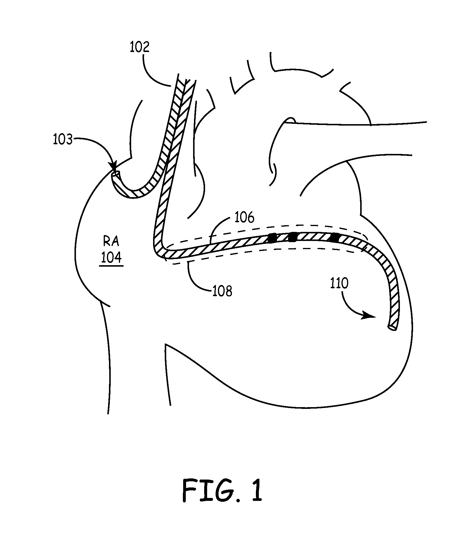
[0016]As depicted in FIG. 1, implantation of a medical electrical lead 102 with...


PUM


Abstract

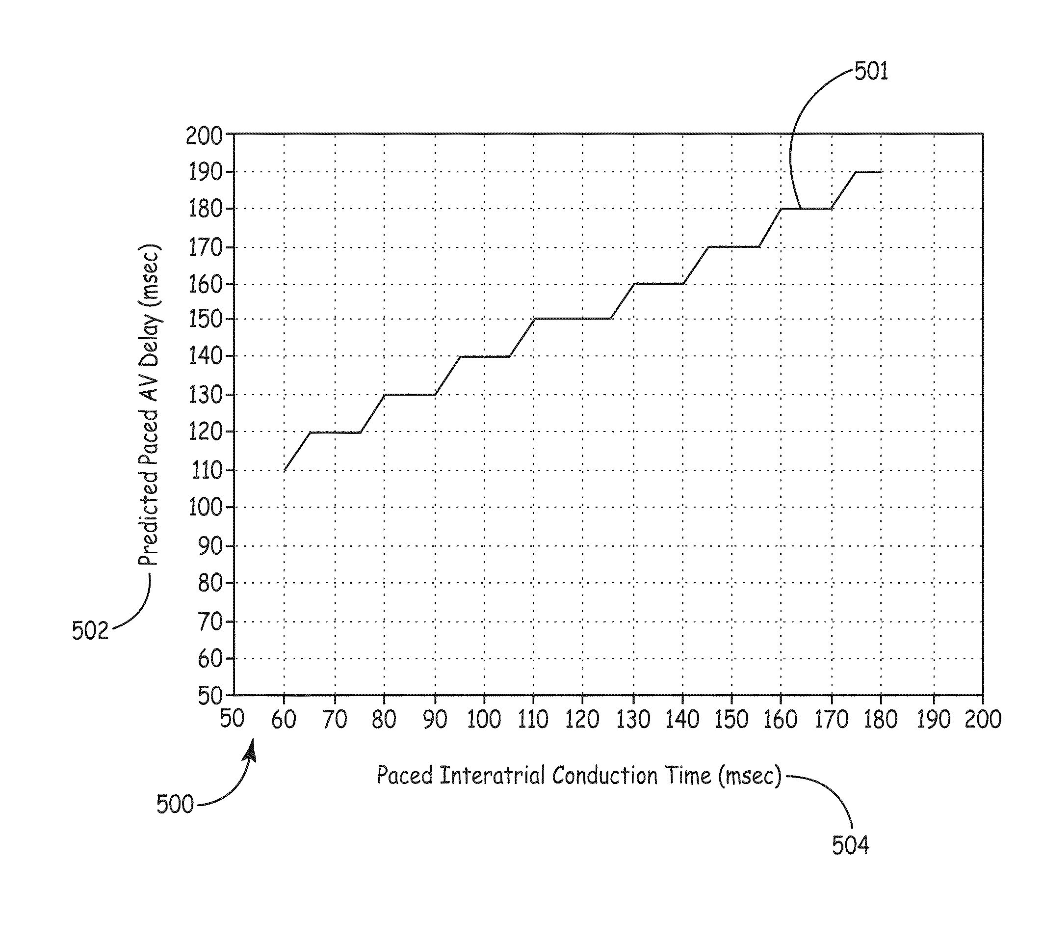
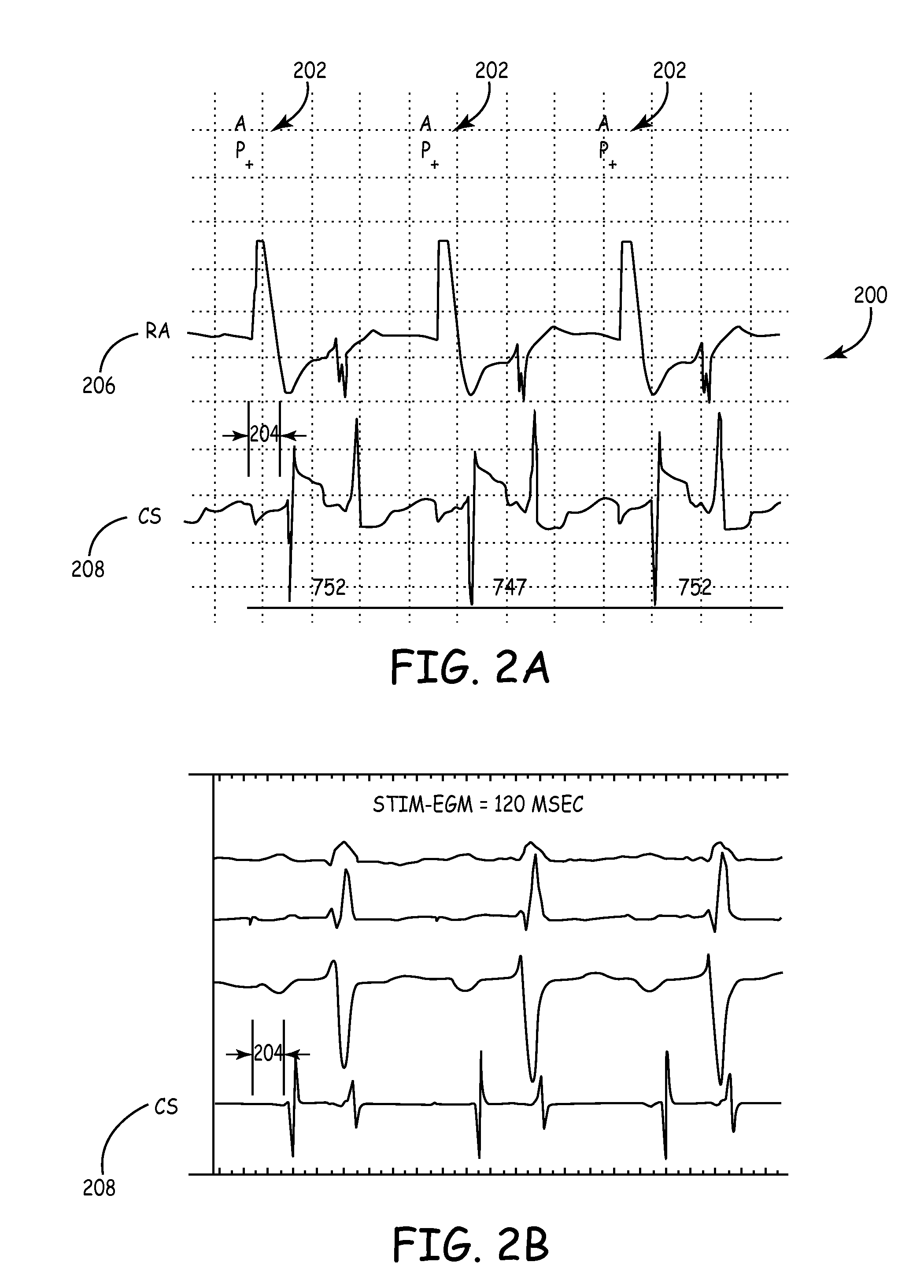
Methods for optimizing the atrio-ventricular (A-V) delay for efficacious delivery of cardiac resynchronization therapy. In CRT devices, the programmed A-V delay starts with detection of electrical activity in the right atrium (RA). Thus, a major component of the A-V delay is the time required for inter-atrial conduction time (IACT) from the RA to the LA. This IACT can be measured during implantation as the time from the atrial lead stimulation artifact to local electrograms in a coronary sinus (CS) catheter. Assuming that the beginning of LA contraction closely corresponds with the beginning of LA electrical activity, the optimal AV delay should be related to the time between the start of RA electrical activity and the start of LA electrical activity plus the duration of LA atrial contraction. Thus ‘during atrial pacing’ the IACT measured at implantation is correlated with the echocardiographically defined optimal paced AV delay (PAV).

Description

FIELD OF THE INVENTION[0001]The present invention relates to methods and apparatus for optimally programming for biventricular implantable pulse generators.BACKGROUND OF THE INVENTION[0002]Congestive heart failure (CHF) is one of the leading causes of cardiovascular morbidity and mortality. With the aging population CHF treatment has become a major public health issue. Recent advances in management of CHF include implantation of biventricular (Bi-V) pacemakers to achieve cardiac resynchronization (CRT). Numerous studies have shown than significant improvements in patients' functional capacity and longevity can be attained when appropriately selected patients receive CRT. Many of the early published trials supporting the benefits of CRT primarily focused on using the patients' intrinsic atrial rate to drive the ventricular pacing rate (VDD mode). However, in clinical practice many CRT recipients are programmed in the dual chamber pacing mode (DDD), which may increase the likelihood o...

Claims


Application Information

Patent Timeline
Patent Type & Authority Patents(United States)
IPC IPC(8): A61N1/365A61N1/368
CPCA61B5/0422A61B5/4884A61N1/056A61N2001/0585A61B5/287
Inventor COLES, JR., JAMES A.UJHELYI, MICHAEL R.RAZAVI, MEHDILEVIN, VADIM
Owner MEDTRONIC INC
Learn More