Eureka AIR delivers breakthrough ideas for toughest innovation challenges, trusted by R&D personnel around the world.

Injection impression tray

a technology of impression tray and injection tray, which is applied in the field of dental impression tray, can solve the problems of distorted impression, difficult to accurately seat the impression tray onto the teeth, and inaccurate impression of missing anatomy

Active Publication Date: 2011-01-18
ALIGN TECH
View PDF15 Cites 38 Cited by
  • Summary
  • Abstract
  • Description
  • Claims
  • Application Information

AI Technical Summary

Problems solved by technology

One problem with existing impression trays lies in the need to load it with impression material and then seat it in the patient's mouth.
This loading process often results in the encapsulation of air bubbles / pockets if the beads are not correctly extruded, which when applied onto the patient, will produce an inaccurate impression with missing anatomy.
Additionally, accurately seating a fully loaded impression tray onto the teeth is difficult and can include misalignment during or after insertion.
If the tray is improperly placed or is accidentally shifted during the setting time, the resulting impression will be distorted.
Further, as a fully loaded tray has to be applied with a substantial (and uncomfortable) amount of force, such force may displace the impression material out of the tray to create a shallow model and show through as the target anatomy enters the confines of the interior tray cavity.
However, inconsistent production of suitable quality impressions using current techniques can decrease the effectiveness or efficiency of many of the wide variety of techniques that make use of dental impressions.

Method used


Image

  • Injection impression tray
  • Injection impression tray
  • Injection impression tray

Examples


Embodiment Construction

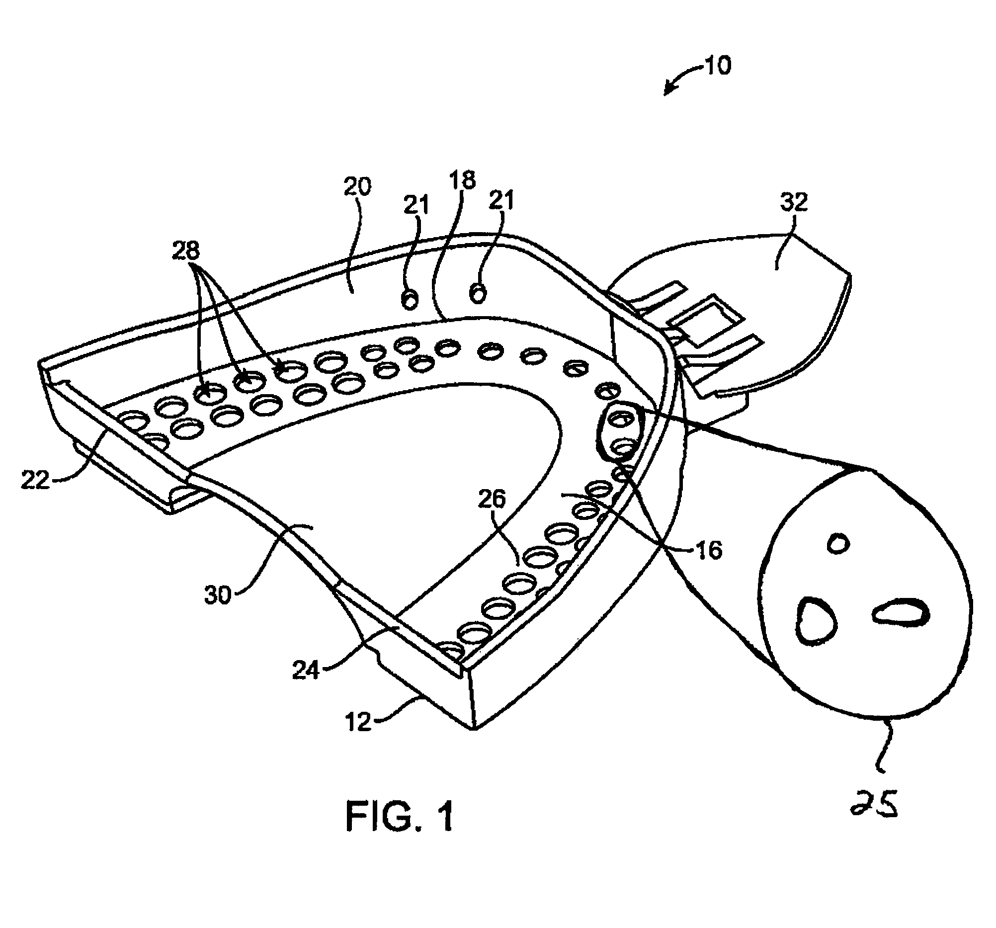
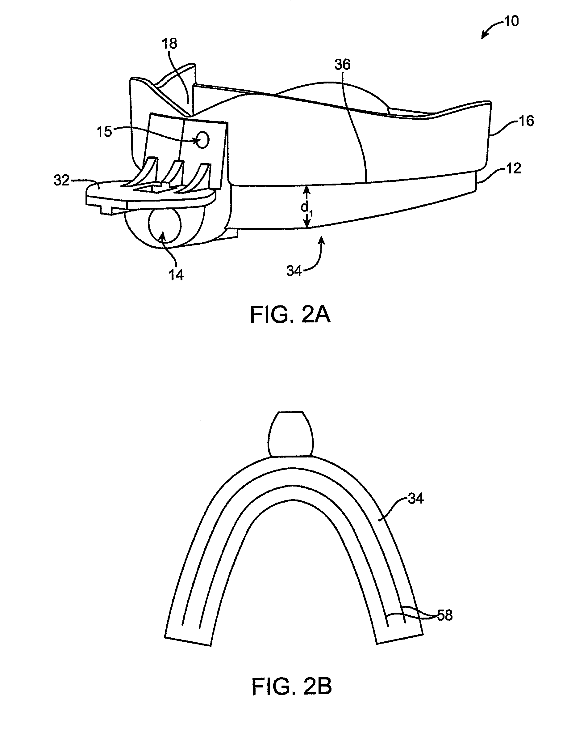
[0013]The present invention relates to an improved dental impression tray and related methods. The tray is designed to more evenly and efficiently flood impression material into the tray and around teeth positioned in the tray, thereby reducing impression inaccuracies, artifacts, air bubbles, and the like. The dental tray of the invention includes a first portion for receiving impression material and a second portion defining a cavity shaped to receive a patient's upper or lower teeth. In use, impression material is loaded into the first portion, where it then flows through the tray, into the teeth receiving portion and distributed to the patient's teeth positioned in the cavity. Rather than having a large, continuously open well, the impression material receiving portion of the tray includes a less-wasteful and more efficient network of distribution channels designed to guide the flow of material throughout the tray. These internal channels include a design and / or layout for improv...


PUM


Abstract

The present invention relates to an improved dental impression tray and related methods. In one embodiment, a dental impression tray includes a first portion for receiving impression material from a source and a second portion is configured for receiving a patient's upper or lower teeth and will at least partial define a cavity shaped to receive the teeth during use. In use, impression material introduced into the first portion can pass through openings and into the second portion and around a patient's teeth.

Description

BACKGROUND OF THE INVENTION[0001]The present invention relates generally to dental impression trays, and more particularly to improved dental impression trays for more evenly and efficiently flooding impression material into the tray and around teeth positioned in the tray.[0002]In the fields of dentistry and orthodontics, a wide variety of procedures and techniques require fabricating a model of a patient's teeth. Modeling teeth often requires making accurate castings of a patient's teeth, tooth surfaces, gingival and other fine details of the patient's dentition. Traditional dental castings are made by loading a dental impression tray or shell with a liquid dental impression material, which is generally a viscous and quick setting material that must be quickly applied to the patient's teeth soon after mixing. The tray loaded with impression material is then inserted into a patient's mouth, and the patient closes their mouth in order to hold the tray in position until the impressio...

Claims


Application Information

Patent Timeline
Patent Type & Authority Patents(United States)
IPC IPC(8): A61C9/00
CPCA61C9/0006
Inventor WU, KENMOSS, JONKIMURA, RYANCAO, HENG
Owner ALIGN TECH
Why Eureka
Eureka Blog
Learn More