
Venting container

a technology of food storage containers and venting containers, which is applied in the field of food storage containers, can solve the problems of poor ability to accommodate a desired amount of produce respiration, added cost and complexity in the manufacture of containers, plastic, microwavable containers, etc., and achieves the effects of preventing splattering of the contents of the container, reducing or eliminating disadvantages and drawbacks, and simple operation of venting

Active Publication Date: 2011-01-11
THE GLAD PROD CO
View PDF24 Cites 57 Cited by
  • Summary
  • Abstract
  • Description
  • Claims
  • Application Information

AI Technical Summary

Benefits of technology

[0011]In another embodiment, the venting means comprises a second and optionally a third venting button, both of which may be selectively actuated along with actuation of the first venting button to provide an enhanced amount of venting through the closure region of the container.
[0013]The present invention substantially reduces or eliminates the disadvantages and drawbacks associated with prior art container base and lid assemblies. As discussed in detail herein, the container designs of the invention include highly effective, simple to operate venting means that prevent splattering of the container contents during microwaving and that also accommodate produce respiration.

Problems solved by technology

One problem associated with conventional, plastic, microwavable containers stems from the rapid temperature changes they must endure.
A further problem often encountered with plastic containers is the poor ability to accommodate a desired amount of produce respiration while maintaining the sealed integrity of the container.
These executions typically result in added cost and complexity in the manufacture of the container.
Additionally, venting structure in the form of complex valves with moving parts is difficult to design into a thermoformed plastic part.
However, in both instances, the container is still subject to leaking, i.e., no longer leak-proof.
The noted container venting practices will usually permit sufficient air and steam to vent during microwaving because the increased pressure within the container will tend to force the container open, increasing any space between the lid and the bowl.
There is still a problem, however, with the splattering of food that can occur through any unsealed region between the lid and base.
Furthermore, once microwaving is complete, any steam present within the container will cool and the pressure in the container will drop significantly as the pressure differential no longer tends to open the container.
This problem can be aggravated by the accumulation of steam or vapor, which can additionally form a vapor seal between the lid and bowl.
The resulting vacuum can permanently damage the container.

Method used


Image

  • Venting container
  • Venting container
  • Venting container

Examples


Embodiment Construction

[0026]Unless defined otherwise, all technical and scientific terms used herein have the same meaning as commonly understood by one having ordinary skill in the art to which the invention pertains.

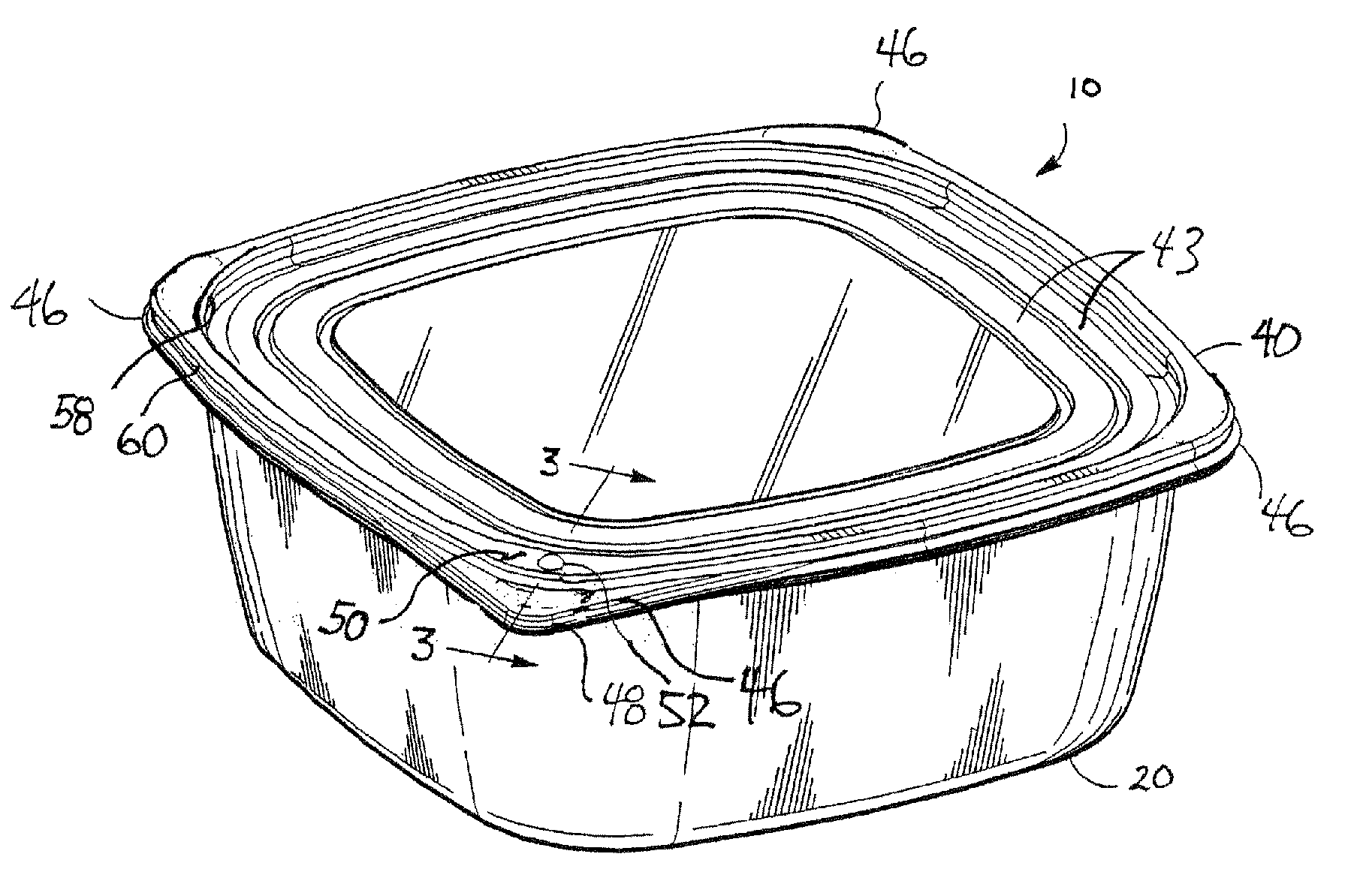
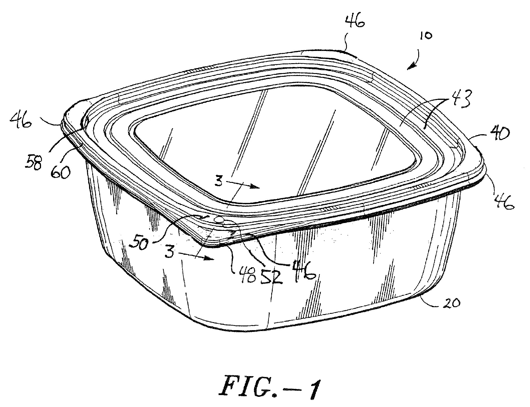
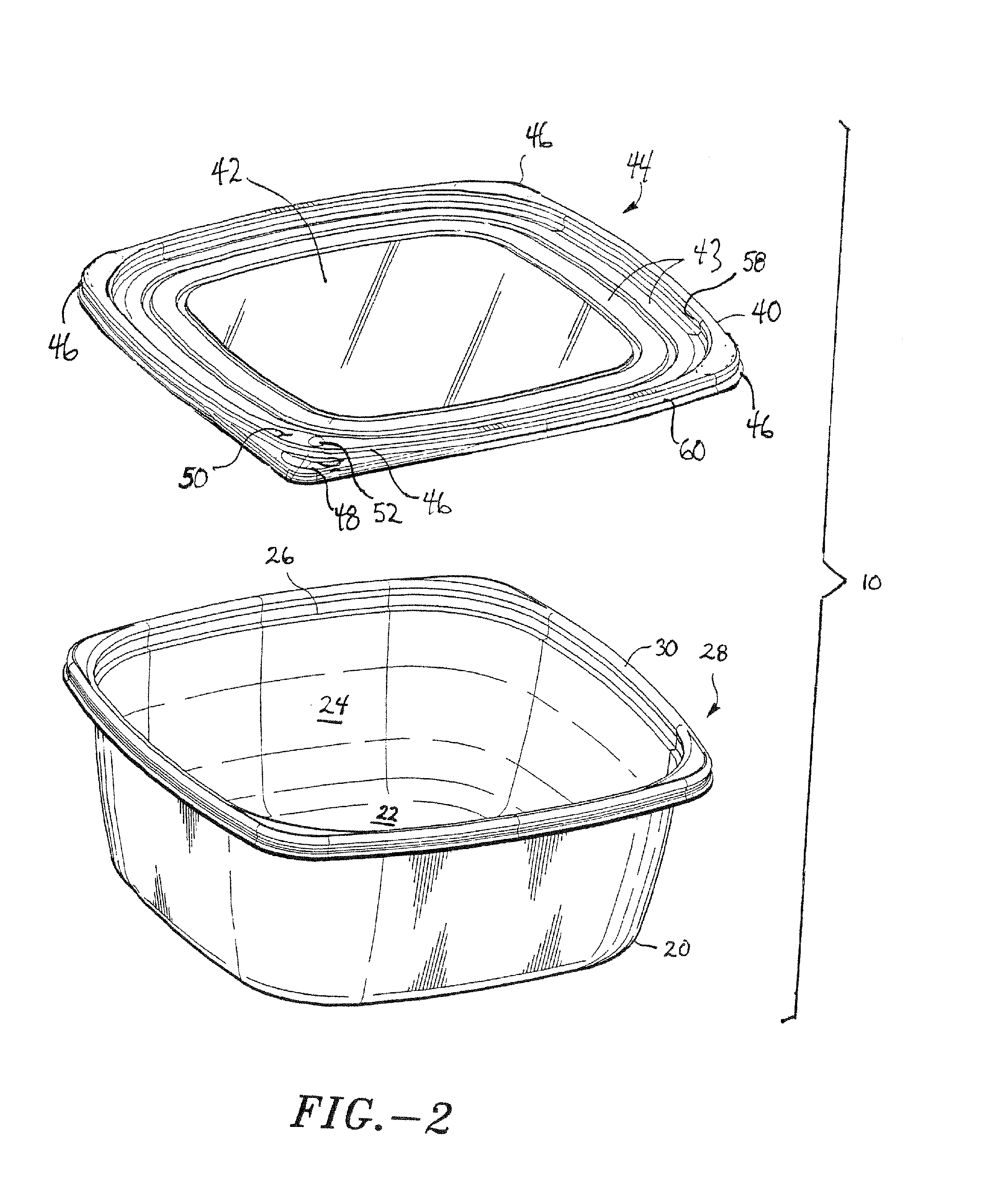
[0027]Turning to the drawings, wherein like reference numerals refer to like elements, a first embodiment of the present invention is illustrated in FIGS. 1 and 2. A container 10 includes a container base 20 and a flexible container lid 40. In the example shown in the Figures, the container 10 is depicted as substantially square with rounded corners. In other embodiments of the present invention, the container 100 has other shapes such as rectangular, circular, or elliptical.

[0028]The container base 20 has a bottom 22 and a sidewall 24 extending from the periphery of the bottom 22. At the termination of the sidewall 24 an outwardly and substantially horizontally extending denesting shoulder 26 is provided, which merges into the base of a closure portion 28. The closure portion 28 has a gene...


PUM

PropertyMeasurementUnit
rotationaaaaaaaaaa
actuation forceaaaaaaaaaa
temperatureaaaaaaaaaa

Abstract

A venting container including a lid and base having an inner cavity and a side wall that terminates in a rim, the lid including a central panel and a peripheral sealing lip that surrounds the panel, the peripheral sealing lip having a generally inverted U-shaped cross section that defines a lid channel into which the container rim fits, the sealing lip including at least one venting feature in the form of a flexible venting button that is adapted to transition from a first position to a second position upon application of an actuation force, the venting button being further adapted and positioned whereby when the container rim is positioned in the lid channel and the venting button is in the first position, sealed engagement of the lid to the container is effectuated and when the venting button is in the second position a venting air passage is provided from the container cavity to the container surroundings. In a second embodiment, the venting feature is in the form of a downwardly protruding venting boss provided to the lid closure and a boss seat formed in the base closure whereby the venting boss is received with the boss seat when the lid is oriented in a first non venting attachment position and the venting boss abuts against a surface of the base closure to provide a vent passage between the lid and base upon removal and repositioning of the lid to a second venting attachment position.

Description

FIELD OF THE PRESENT INVENTION[0001]The present invention relates generally to food storage containers. More particularly, the invention relates to a food storage container including a lid, a base and a venting feature.BACKGROUND OF THE INVENTION[0002]Food storage containers are well known in the art. The noted containers generally include a lid that is selectively detachable from a bowl and are commonly designed to provide a variety of features, including being reusable, disposable, microwavable, and the like.[0003]Numerous types of bowl and lid assemblies and means for effecting sealable engagement of a lid on a bowl have been devised. Illustrative are the containers and engagement means disclosed in U.S. Pat. Nos. 6,170,696 and 6,868,980.[0004]One problem associated with conventional, plastic, microwavable containers stems from the rapid temperature changes they must endure. The container must be permitted to vent during microwaving due to the high pressures that arise as moistur...

Claims


Application Information

Patent Timeline
Patent Type & Authority Patents(United States)
IPC IPC(8): B65D41/16B65D51/16B65D41/18
CPCB65D51/1627B65D51/1672B65D41/18B65D43/08B65D51/16
Inventor MAXWELL, JASON R.
Owner THE GLAD PROD CO
Learn More