
Method and device for producing dental prosthesis elements

a dental prosthesis and element technology, applied in dental prosthetics, sports equipment, projectors, etc., can solve the problems of high cost, high complexity, and inability to meet aesthetic requirements and achieve good monitoring of dental prosthetic items

Inactive Publication Date: 2011-01-04
SIRONA DENTAL SYSTEMS
View PDF20 Cites 67 Cited by
  • Summary
  • Abstract
  • Description
  • Claims
  • Application Information

AI Technical Summary

Benefits of technology

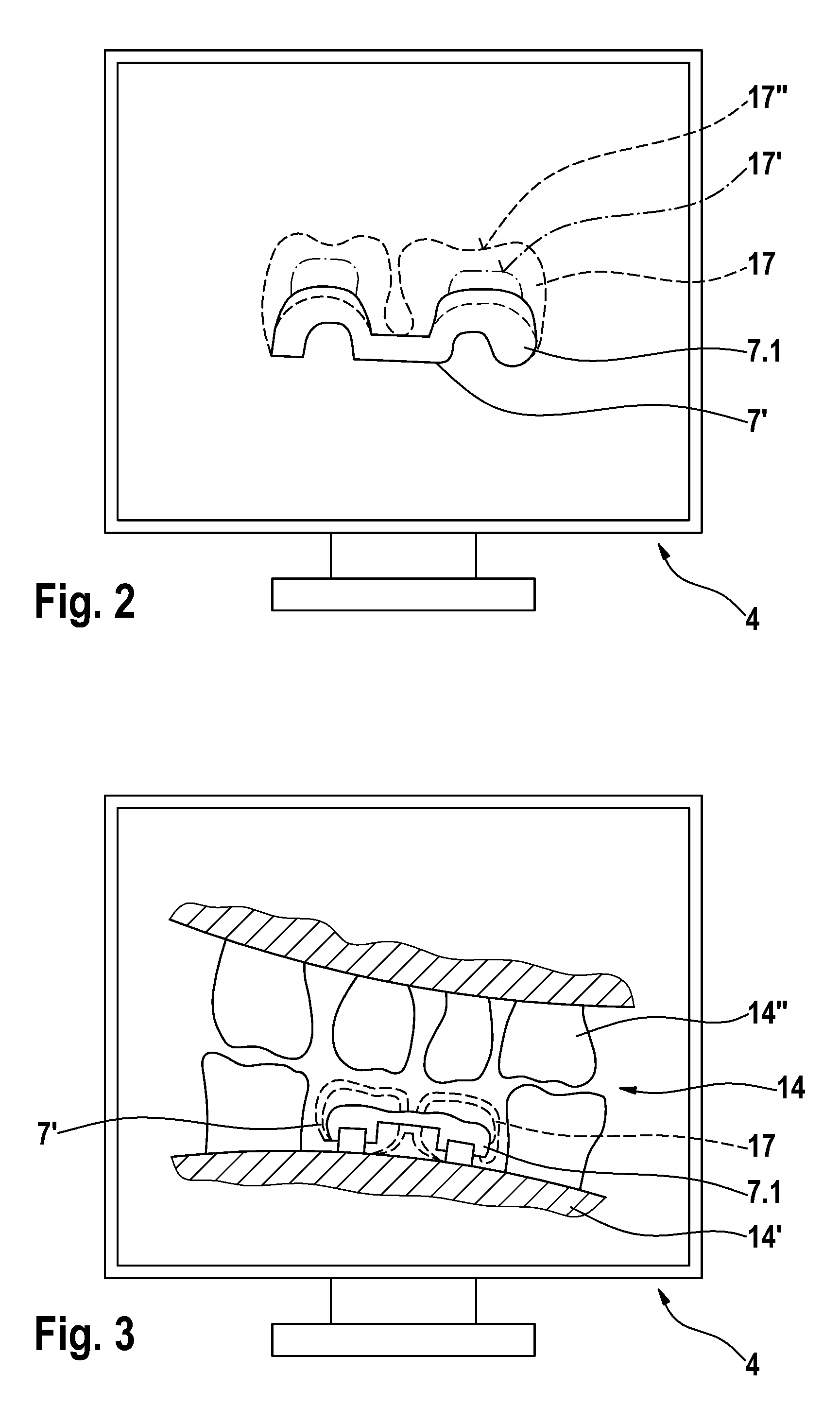
[0016]The advantage of this method is that the dental technician on the one hand retains complete aesthetic control of the production of the dental prosthetic item and, on the other hand, has the assurance, by effecting comparison with a digital design, of producing an accurately fitting, high-quality dental prosthetic item in an economical manner. Moreover, he does not require any more models of the dental situation other than the design data.
[0048]Furthermore, another advantage of the device is that the dental technician no longer requires physical impressions of the dental situation. These impressions are frequently inaccurate, since they widen when being removed from the patient's mouth and then change their size during the drying process. The expected fitting accuracy is less than or at most equal to that achieved in a high-precision intraoral three-dimensional scan.

Problems solved by technology

The disadvantages of these methods are that, firstly, the contact surfaces are at most as precise as the situation model, which lacks proper dimensional accuracy due to the fact that an impression is made and the resulting model dries out.
Secondly, the occlusion can be examined only with the aid of a mechanical articulator, so that flawless functional efficiency of the dental prosthetic item will greatly depend on the skill of the dental technician.
The disadvantage of fully automatic production methods is that the dental prosthetic items only partially meet the aesthetic requirements, since a natural tooth has complex optical properties resulting from its multi-layered structure.
The disadvantage of the method described above is that the preparation of a model based on digital data is highly elaborate.

Method used


Image

  • Method and device for producing dental prosthesis elements
  • Method and device for producing dental prosthesis elements
  • Method and device for producing dental prosthesis elements

Examples


Embodiment Construction

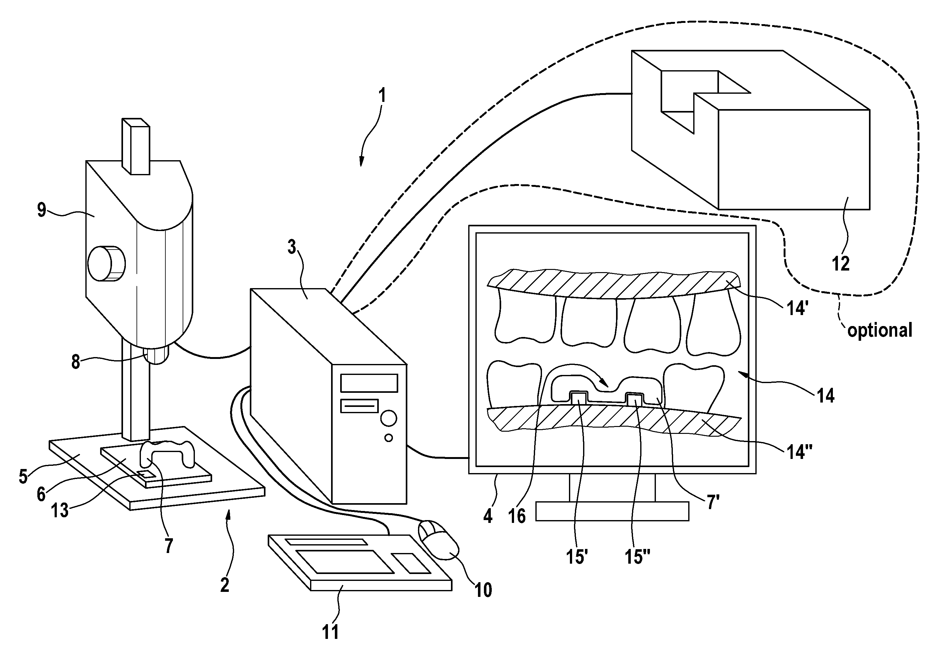
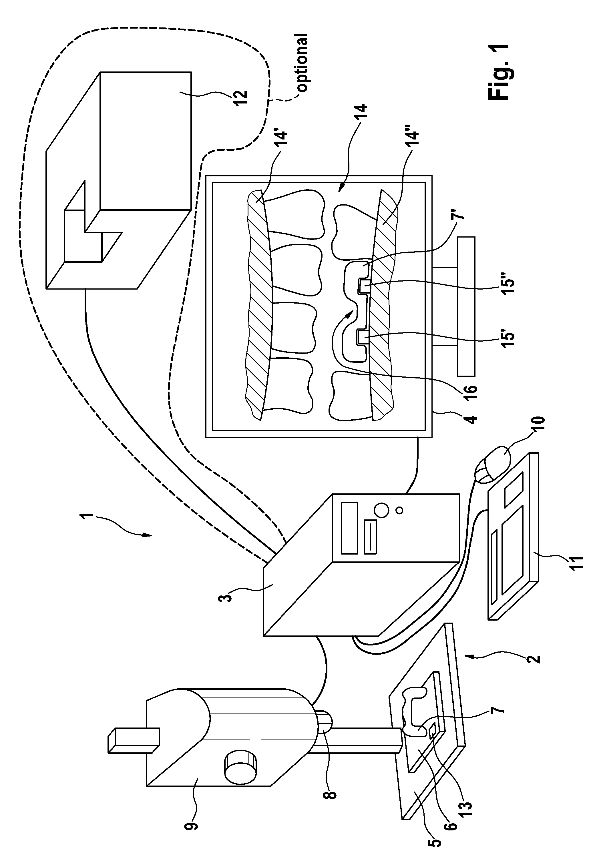
[0054]FIG. 1 shows a device 1 used for the partial manual production of a dental prosthetic item 7. The device 1 substantially comprises a 3D scanning device 2, a computer 3, and a monitor 4.

[0055]A holding device 6 holding a dental prosthetic item 7, which is accurately positioned thereon and which requires finishing, is located on the base plate 5 of the 3D scanning device 2. The dental prosthetic item 7 is positioned by the holding device 6 in the field of view of scanning optics 8 of the three-dimension scanning device 2. The scanning optics 8 are accommodated in a vertically adjustable housing 9 of the 3D scanning device 2 and are preferably designed to be telecentric.

[0056]The 3D scanning device 2 is connected to the computer 3, which is inputted via a mouse 10 and a keyboard 11. The computer 3 itself is connected to the monitor 4.

[0057]Optionally, the computer 3 can be connected to a grinding machine 12 adapted to effect computer-aided machining of parts of the dental prosthe...


PUM


Abstract

A method for producing a dental prosthesis element wherein construction relating to the dental prosthesis element is recorded together with measurement data relating to the dental prosthesis element and is reproduced on a display, the measurement data having been recorded by a three-dimensional measurement device. A 3D data record of the tooth situation can be reproduced on the display instead of the construction data. A device for the partial manual treatment of the dental prosthesis element includes a three-dimensional measurement device, a display, and a computer unit for the correlation and comparison of two data records and for graphically presenting the data generated by the comparison.

Description

BACKGROUND OF THE INVENTION[0001]1. Field of the Invention[0002]The invention relates to a method for the production of a dental prosthetic item, in which method the dental prosthetic item is machined manually.[0003]The invention further relates to a method for the production of a dental prosthetic item comprising a framework and a superstructure.[0004]Furthermore, the invention relates to devices for partial manual machining of a dental prosthetic item.[0005]2. Prior Art[0006]Methods are known in the prior art, in which dental prosthetic items are produced using computer-aided design and production techniques to various extents.[0007]The older prior methods dispense entirely with the use of computers. In most cases, an impression of the dental situation is made both of the jaw that requires treatment and of the opposing jaw. This impression is used as the basis for the production of a positive model, on which a dental technician will produce the dental prosthetic items in several l...

Claims


Application Information

Patent Timeline
Patent Type & Authority Patents(United States)
IPC IPC(8): G06F19/00G03B21/60G06K9/00A61B6/14A63B57/00
CPCA61C13/0004A61C9/004A61C9/0046B33Y80/00B33Y50/00
Inventor PFEIFFER, JOACHIM
Owner SIRONA DENTAL SYSTEMS
Learn More