
Submersible direct-current electric motor

a direct-current electric motor and submerged technology, applied in the direction of machines/engines, flexible member pumps, positive-displacement liquid engines, etc., can solve the problems of limited rotation speed control range, considerable reactive power consumption under low-load conditions, and complicated speed control system

Inactive Publication Date: 2010-12-28
SCHLUMBERGER TECH CORP
View PDF14 Cites 3 Cited by
  • Summary
  • Abstract
  • Description
  • Claims
  • Application Information

AI Technical Summary

Benefits of technology

The design provides a simple control system, wide rotation speed range, and reliable operation in conductive fluids by eliminating short circuits and managing torque, ensuring the motor's durability and efficiency as a submersible pump drive.

Problems solved by technology

The disadvantages of induction motors include a limited rotation speed control range and considerable reactive power consumption under the low-load conditions.
Moreover, the speed control system is rather complicated due to the need to adjust the frequency of current, and the presence of three wires in the winding makes this adjustment a rather difficult process.
Operation of direct-current motors is based on the interaction between current conductors and magnets, which results in occurrence of electromagnetic torque.
However, the main disadvantage of these motors when used as submersible pump drives is that a short circuit occurs between the brushes and the collector when the motors are submerged into a fluid, particularly, into an electrically conducting fluid.
This may cause damage to the brushes and / or to the collector.

Method used


Image

  • Submersible direct-current electric motor
  • Submersible direct-current electric motor
  • Submersible direct-current electric motor

Examples


Embodiment Construction

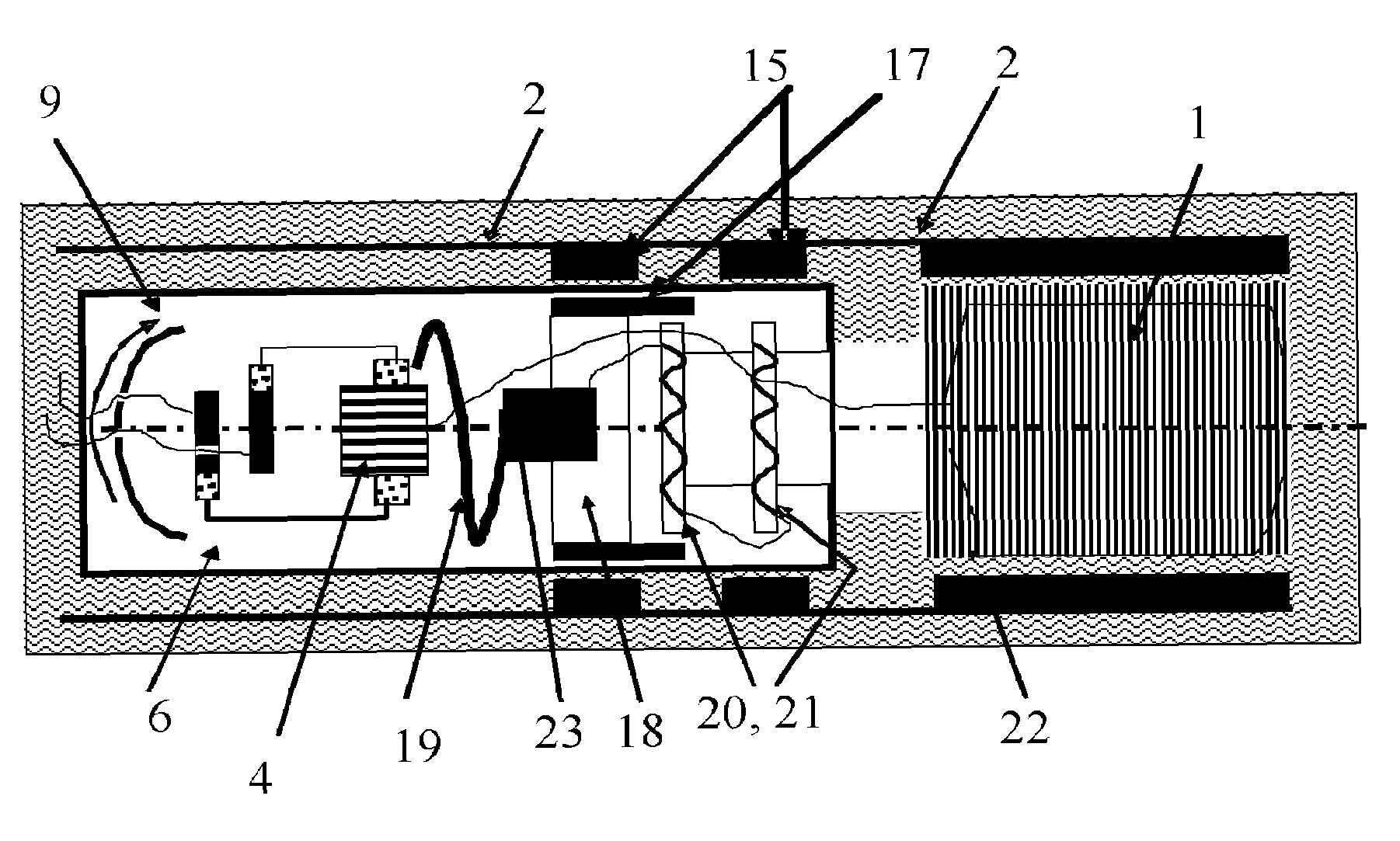
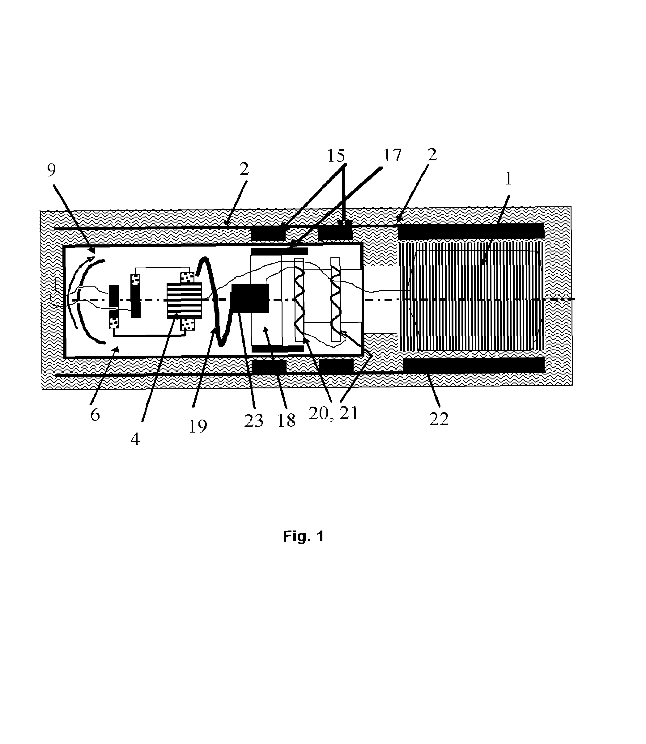
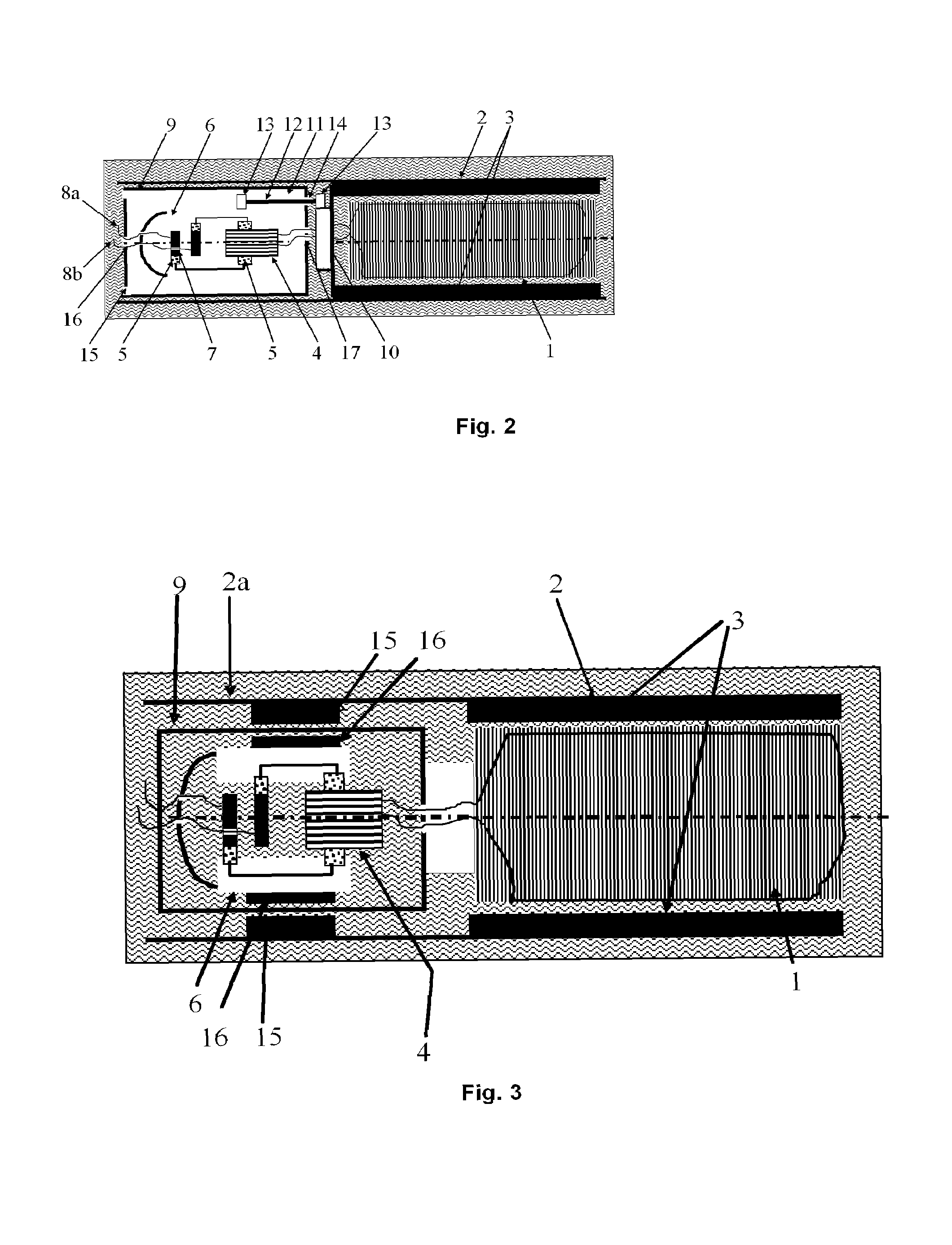
[0030]The submersible direct-current electric motor corresponding to the invention includes an armature winding (1) which is fixed and forms the central part of the motor. The armature winding (1) is enclosed in the motor housing (2) which is capable of rotating around the armature winding (1). The housing (2) carries permanent magnets (3) which form an excitation flux. Alternatively, it is possible to use excitation windings instead of permanent magnets. Further, the fixed armature winding (1) is connected through wires to a collector (4) which is also fixed. Brushes (5) installed on a rotating ring (6) interact with the collector (4). The brushes (5) also interact with corresponding solid fixed collector rings (7) which are connected to respective polarity wires (8a, 8b) of the power cable. Each brush (5) can be made of two separate brushes connected to each other. One of these brushes interacts with the collector (4) and the other one interacts with the corresponding collector ri...


PUM


Abstract

The claimed invention relates to a submersible direct-current electric motor to be used, in particular, for driving a submersible pump in downhole oil production. The claimed motor includes a fixed armature winding; a housing which encloses the armature winding and rotates around it; magnetic field generation means which are fixed in the housing and interact with the armature winding to generate electromagnetic torque; a fixed collector which is electrically connected to the armature winding; brushes which rotate around the fixed collector and are connected to the external electric circuit. The fixed collector and the brushes rotating around it are enclosed in an insulating chamber. The technical result consists in the elimination of the risk of a short circuit between the brushes and the collector of the direct-current motor when it is used as a submersible motor.

Description

TECHNICAL FIELD[0001]The invention relates to a submersible direct-current electric motor to be used, in particular, as a submersible pump drive in downhole oil production.BACKGROUND ART[0002]Presently, induction motors are used as submersible motors in various applications, including driving submersible electric pumps in oil fields. In some applications, an induction motor is a single-phase alternating-current motor. But its three-phase model is used more frequently. The induction motor operation philosophy is based on the interaction between a rotating magnetic field that occurs when three-phase alternating current passes through the stator windings, and the current induced by the stator field in the rotor windings, which results in occurrence of mechanical forces that make the rotor rotate in the direction of the rotating field rotation, provided that the rotor rotation speed is lower than the field rotation speed. So, the rotor rotates asynchronously with respect to the field. T...

Claims


Application Information

Patent Timeline
Patent Type & Authority Patents(United States)
IPC IPC(8): H02K5/10
CPCF04B47/06F04D13/10H02K23/62
Inventor ORBAN, JACQUES
Owner SCHLUMBERGER TECH CORP
Learn More