
Eyeball locating method and system

a technology of eyeball locating and eyeball, applied in the field of eyeball locating methods and systems, can solve the problems of inability to conveniently and real-time control the computer, inconvenient handling the computer, and inability to execute complex control behaviors, so as to increase the successful rate of eyeball locating and be used more conveniently

Active Publication Date: 2010-12-14
TCL CHINA STAR OPTOELECTRONICS TECH CO LTD
View PDF8 Cites 6 Cited by
  • Summary
  • Abstract
  • Description
  • Claims
  • Application Information

AI Technical Summary

Benefits of technology

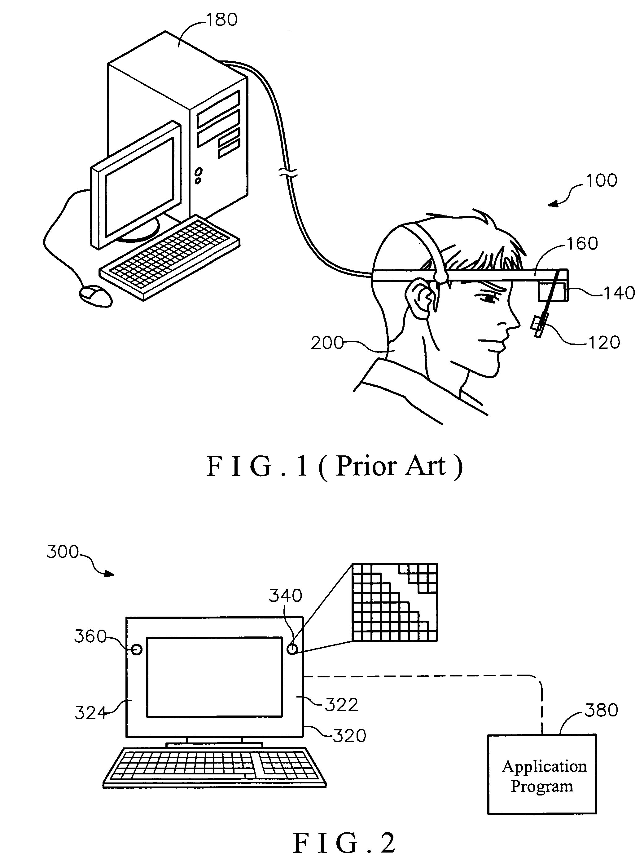
The present invention provides an eyeball locating method and system that can increase the success rate of eyeball locating and make it more convenient to use. The method involves shining light on the eye white and pupil, detecting the reflected light, and calculating the measured characteristic value of the pupil based on the default characteristic value of the pupil shown in a default graph. The measured characteristic value is then compared with the default characteristic value to determine the change of the pupil. The system includes a matrix optical sensor for detecting the reflected light, a display panel for shining the light, and an application program for controlling the matrix optical sensor and calculating the characteristic value. The technical effect of the invention is to provide a more accurate and reliable method for locating the eyeball.

Problems solved by technology

Computer makes people's daily life more and more convenient, but for most disabled men, it is rather inconvenient to handle computer.
The common disadvantage among these control methods is that they are not capable of executing complex control behaviors, and they are also unable to control the computer conveniently and real-timely because the control signal needs complex identification and longer processing period.
However this system influences the measurement of the electrical signal easily due to sweat.
The difficulty of the optical detection is when capturing the pupil image, the contrast ratio between the pupil and the eye white is too low to measure, especially under the condition of glasses obstruct, outer light disturb or eyeball pathological changes.
In conclusion, the conventional eyeball tracking system 100 is limited in use and has low resolution, which makes it hard to apply in the view or browsing equipments or general medical occasion.

Method used


Image

  • Eyeball locating method and system
  • Eyeball locating method and system
  • Eyeball locating method and system

Examples


Embodiment Construction

[0032]In the following detailed description of the preferred embodiments, reference is made to the accompanying drawings which form a part hereof, and in which are shown by way of illustration specific embodiments in which the invention may be practiced. In this regard, directional terminology, such as “top,”“bottom,”“front,”“back,” etc., is used with reference to the orientation of the Figure(s) being described. The components of the present invention can be positioned in a number of different orientations. As such, the directional terminology is used for purposes of illustration and is in no way limiting. On the other hand, the drawings are only schematic and the sizes of components may be exaggerated for clarity. It is to be understood that other embodiments may be utilized and structural changes may be made without departing from the scope of the present invention. Also, it is to be understood that the phraseology and terminology used herein are for the purpose of description an...


PUM


Abstract

An eyeball locating system includes a display panel, an application program and a matrix optical sensor. The matrix optical sensor is disposed in the display panel. The application program controls the matrix optical sensor, executing an eyeball locating method to measure the movement of an eyeball including an eye white and a pupil. The method includes: providing a default graph showing the change of light energy; defining a default characteristic value of the pupil according to the default graph; shining light on the eye white and the pupil, a part of the light reflected by the eye white and the pupil to form a reflecting light; detecting the reflecting light energy to form a measured graph showing the change of reflected light energy; calculating a measured characteristic value according to the measured graph; and comparing the default with the measured characteristic values to determine the change of the pupil.

Description

BACKGROUND OF THE INVENTION[0001](1) Field of the Invention[0002]The present invention relates to an eyeball locating method and system, particularly to an eyeball locating method and system using an optical sensor for determining the light reflected by the surface of the eyeball.[0003](2) Description of the Prior Art[0004]Computer makes people's daily life more and more convenient, but for most disabled men, it is rather inconvenient to handle computer.[0005]To help the disabled men to handle computer, several control methods of the man-machine interface system have been developed in the world, such as hand joint control, voice control, electromyogram (EMG) behavior, shoulder control, gassing and so on. The common disadvantage among these control methods is that they are not capable of executing complex control behaviors, and they are also unable to control the computer conveniently and real-timely because the control signal needs complex identification and longer processing period...

Claims


Application Information

Patent Timeline
Patent Type & Authority Patents(United States)
IPC IPC(8): A61B3/14A61B3/00
CPCA61B3/113G06F3/013
Inventor CHEN, YU-CHIA
Owner TCL CHINA STAR OPTOELECTRONICS TECH CO LTD
Learn More