
Heating flange with geometrically stable structure

a technology of geometric stability and heating flange, which is applied in the direction of space heating and ventilation details, fuel heating, air heaters, etc., can solve the problems of manufacturing, mounting and maintenance, and achieve the effect of small installation size, good access to mounting points, and large flow cross-section

Inactive Publication Date: 2010-12-07
DAVID & BAADER DBK
View PDF9 Cites 0 Cited by
  • Summary
  • Abstract
  • Description
  • Claims
  • Application Information

AI Technical Summary

Benefits of technology

[0009]The object of the invention under consideration therefore is to create an improved heating flange of a simple and robust construction that is easier to manufacture, mount and maintain.
[0053]Very simple, economical and quick manufacture of the frame of the heating flange, particularly with the recesses at the leg pieces and the mounting flange attached in one-piece, is possible by manufacturing it as a cast part, preferably as an aluminium pressure-cast part. Alternatively, the manufacture can also be done as an extruded profile with subsequent mechanical finishing.

Problems solved by technology

With the known heating flanges, however, the manufacture, mounting and maintenance are problematic.

Method used


Image

  • Heating flange with geometrically stable structure
  • Heating flange with geometrically stable structure
  • Heating flange with geometrically stable structure

Examples


second embodiment

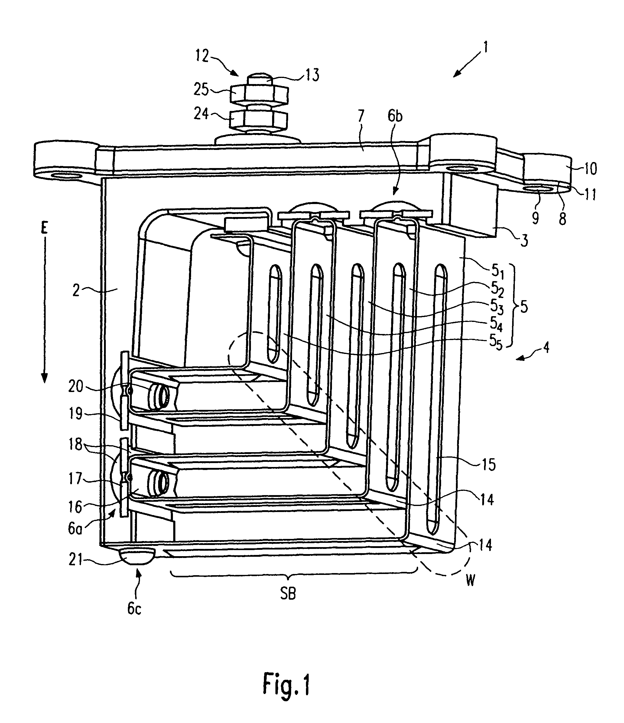
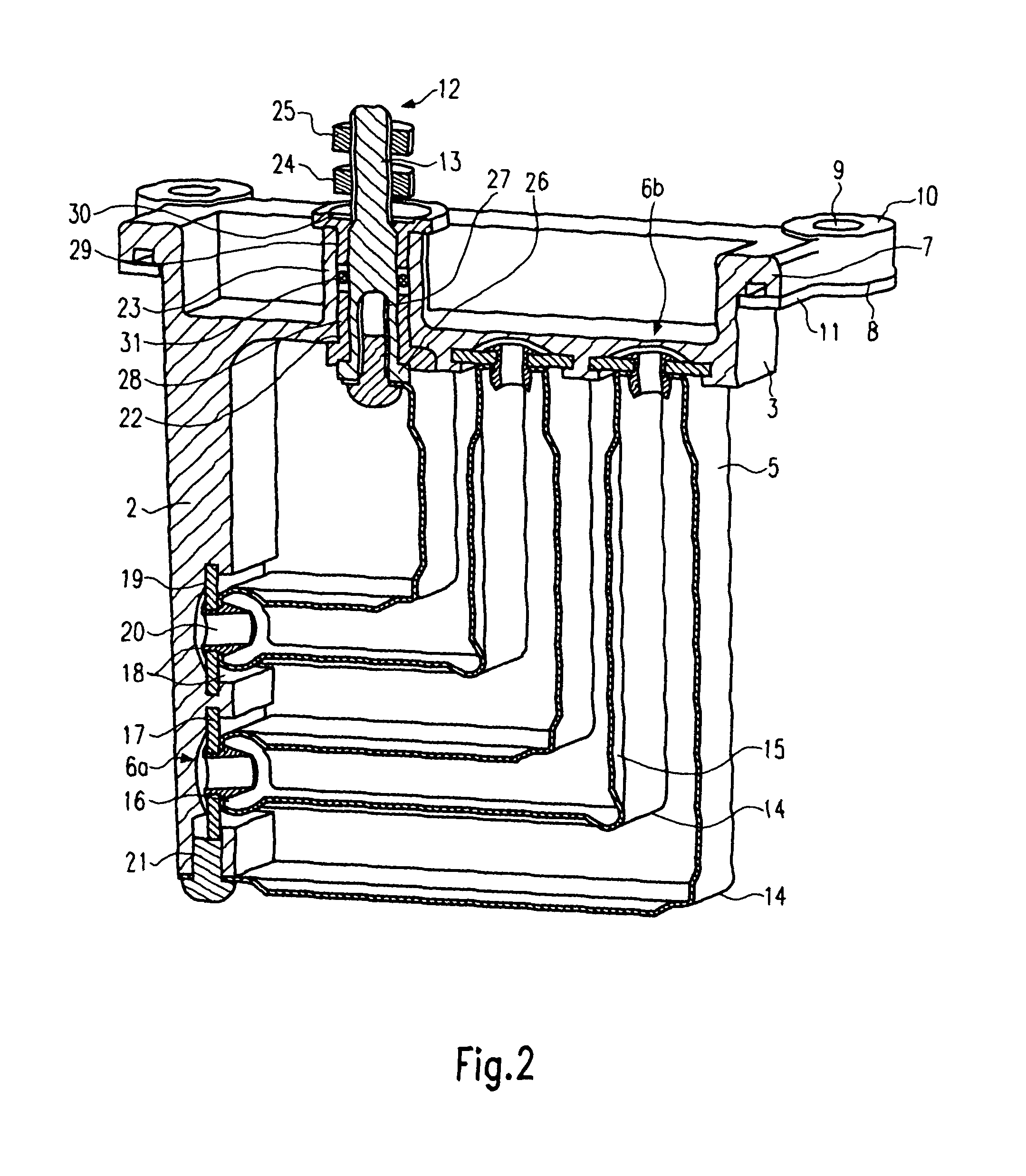
[0091]FIG. 3 shows a schematic perspective depiction of the heating flange according to the invention, and indicates the intake line A. For the sake of clarity, only the differences with respect to the above-described embodiment are explained in the following. For parts whose configuration and / or function is similar or identical to parts in the previous embodiment, the same reference numbers are used as in FIG. 1.

[0092]The intake line A is depicted in sectioning in the area of the heating flange 1. It can be seen that the mounting leg piece 3 lies outside the intake line A, whereas the heat conductor 5 is arranged within the intake line A. In this way, the mounting leg piece 3 covers the mounting opening M in the intake line A. No further explanation is given here for the mounting and sealing of the heating flange 1 according to the invention in the mounting opening M of the intake line A.

[0093]The heat conductor 5 of FIG. 3 is arranged with a curved shape and extends from a first m...

third embodiment

[0097]FIG. 4 shows a schematic side-view of the heating flange according to the invention. For the sake of clarity, only the differences with respect to the above-described embodiments are explained in the following. For parts whose configuration and / or function is similar or identical to parts in the previous embodiment, the same reference numbers are used as in the preceding figures.

[0098]The frame of the heating flange is again provided with two leg pieces 2 and 3, which are directly connected to each other at the ends and that form an open, this time obtuse, angle in the cross-section of flow.

[0099]The heat conductor 5 is formed as a meandering strip heater, which is run back and forth between mounting points 6a and 6b of the retaining leg pieces 2 and 3. In contrast to the heat conductor 5 of FIG. 1 and FIG. 2, the heat conductor 5 in FIG. 4 has two kinks 14a and 14b in a section between the one mounting point 6a on the insertion leg piece 2 and the other mounting point 6b on t...

fourth embodiment

[0104]FIG. 5 shows the schematic side-view of a Again, only the differences with respect to the above-described embodiments are explained. For parts whose configuration and / or function is similar or identical to parts in the previous embodiments, the same reference numbers are used as in the preceding figures.

[0105]This time, the frame of the heating flange is designed with an essentially T-shaped cross-section. At the same time, the longitudinal axes of the two leg pieces 2 and 3 are arranged roughly perpendicular to one another and the one end of the insertion leg piece 2 is directly connected to roughly the centre of the mounting leg piece 3. Consequently, the two leg pieces 2 and 3 span a heating flange with two cross-sections of flow that lie next to one another.

[0106]In each of the two cross-sections of flow, a separate heat conductor 5 and 5′ extends as a meandered strip heater back and forth between mounting points 6 on the leg pieces 2 and 3. The two heat conductors 5 und ...


PUM


Abstract

Heating flange (1) for heating a flow of gas as it flows though a cross-section of flow (S), wherein the heating flange (1) is designed such that it can be inserted or interposed in an intake line (A) of an internal combustion engine and has at least one heat conductor (5) that extends through the cross-section of flow (S) from a mounting point (6a) to an immediately following further mounting point (6b) on the heating flange (1), as well as a retaining leg piece (2), which is provided with at least one of the mounting points (6a). In order to create an improved heating flange of a simple and robust construction that is easier to manufacture, mount and maintain, according to the invention, it is provided for the longitudinal axis of the one retaining leg piece (2) to form a triangle, on the one hand, with two heating leg pieces (5a, 5b) of the heat conductor (5) between the one mounting point (6a) and the other mounting point (6b), which is likewise arranged on the one retaining leg piece (2), or, on the other hand, with the longitudinal axis of a further retaining leg piece (3), on which the further mounting point (6b) is provided, as well as with the straight line through the one (6a) and the other mounting point (6b).

Description

FIELD OF THE INVENTION[0001]The invention under consideration relates to a heating flange for heating a flow of gas that flows through a cross-section of flow, wherein the heating flange is designed so that it can be inserted or interposed in an intake line of an internal combustion engine and so that it has at least one heat conductor, which extends through the cross-section of flow from one mounting point to an immediately following further mounting point on the heating flange, as well as a retaining leg piece, which is provided with at least one of the mounting points.BACKGROUND OF THE INVENTION[0002]Heating flanges of the generic kind are principally used for heating the flow of intake air in an intake line leading to an internal combustion engine. They are especially used in diesel engines in order to make a cold start easier.[0003]In DE 105 15 533 C2, a heating flange is described in which a heat conductor running in a meandering shape is mounted on a carrier rod. The heat con...

Claims


Application Information

Patent Timeline
Patent Type & Authority Patents(United States)
IPC IPC(8): H05B3/06F24D13/00
CPCF02M31/13Y02T10/126Y02T10/12
Inventor GSCHWIND, THOMASPRONER, MATHIAS
Owner DAVID & BAADER DBK
Learn More