
Iliac artery stent graft

a technology for iliac arteries and stents, which is applied in the field of medical devices, can solve the problems of no practical way of performing endovascular, damage or defective portions of vasculature, and extremely difficult access

Active Publication Date: 2010-12-07
COOK MEDICAL TECH LLC
View PDF13 Cites 71 Cited by
  • Summary
  • Abstract
  • Description
  • Claims
  • Application Information

AI Technical Summary

Benefits of technology

The invention is a stent graft that includes a main tubular body and a side branch tubular body that is affixed into the main tubular body. The main tubular body has an external zig-zag stent and an internal zig-zag stent at its distal end. The side branch tubular body has an external zig-zag stent and an internal zig-zag stent. The stent graft also includes a reinforcing ring around the proximal end of the main tubular body and stitched thereto. The technical effect of this invention is to provide a stent graft that can effectively repair damaged blood vessels in a patient's body.

Problems solved by technology

In many cases, however, such a damaged or defective portion of the vasculature may include a branch vessel such as an internal iliac artery.
Bypassing such a branch vessel without providing blood flow into it can cause problems and hence it has been proposed to provide a side branch on a stent graft which when deployed is positioned over the opening to the internal iliac artery and then another stent graft can be deployed through the side branch into the internal iliac artery to provide a blood flow path to the internal iliac artery.
The internal iliac artery which extends from the common iliac artery below the aortic bifurcation is for all intents and purposes a blind vessel because there is no practical way of performing an endovascular minimally invasive procedure into that vessel other than by entry from the common iliac artery.
There have been proposals to deploy a branched stent graft into the common iliac artery via a femoral artery from a femoral incision with the branched stent graft having a side arm to extend into or at least adjacent the internal iliac artery, however, the use of such devices is very dependent upon favourable layout of the arteries and in many cases, access is extremely difficult.

Method used


Image

  • Iliac artery stent graft
  • Iliac artery stent graft
  • Iliac artery stent graft

Examples


Embodiment Construction

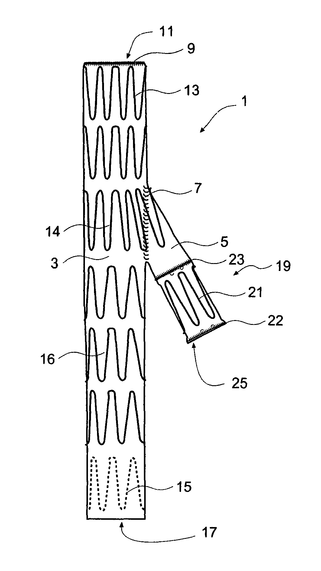
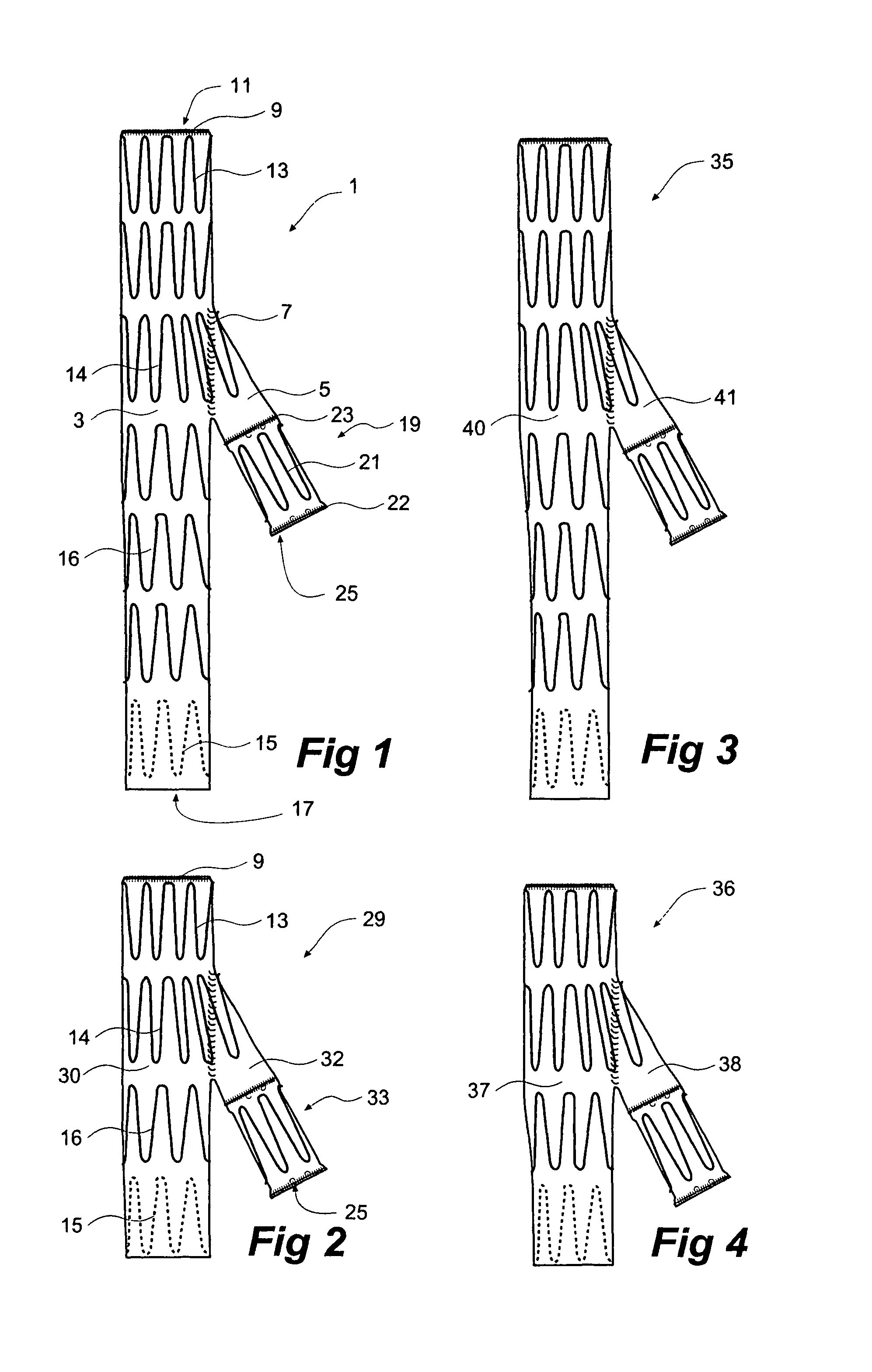
[0033]Now looking more closely at the drawings and in particular FIG. 1 it will be seen that a stent graft 1 comprises a tubular body 3 with a side arm 5, also a tubular body, stitched into an aperture in the main body 3 at 7 so as to allow fluid communication from the lumen of the main body into the lumen of the side arm 5. The main tubular body 3 has a reinforcing ring arrangement 9 at its proximal end 11. The construction of the reinforcing ring 9 will be discussed in relation to FIG. 10. The tubular body 3 also has a number of external zig-zag self-expanding stents 13, 14 and 16 along its length and an internal self-expanding zig-zag stent 15 at its distal end 17.

[0034]PCT Patent Publication WO 2006 / 034276 entitled “Side Branch Stent Graft” includes discussion of one method of connection of a side arm to a main tubular body in a stent graft and the disclosure of this patent specification is incorporated herewith in its entirety.

[0035]On the side arm 5 there is a connection socke...


PUM


Abstract

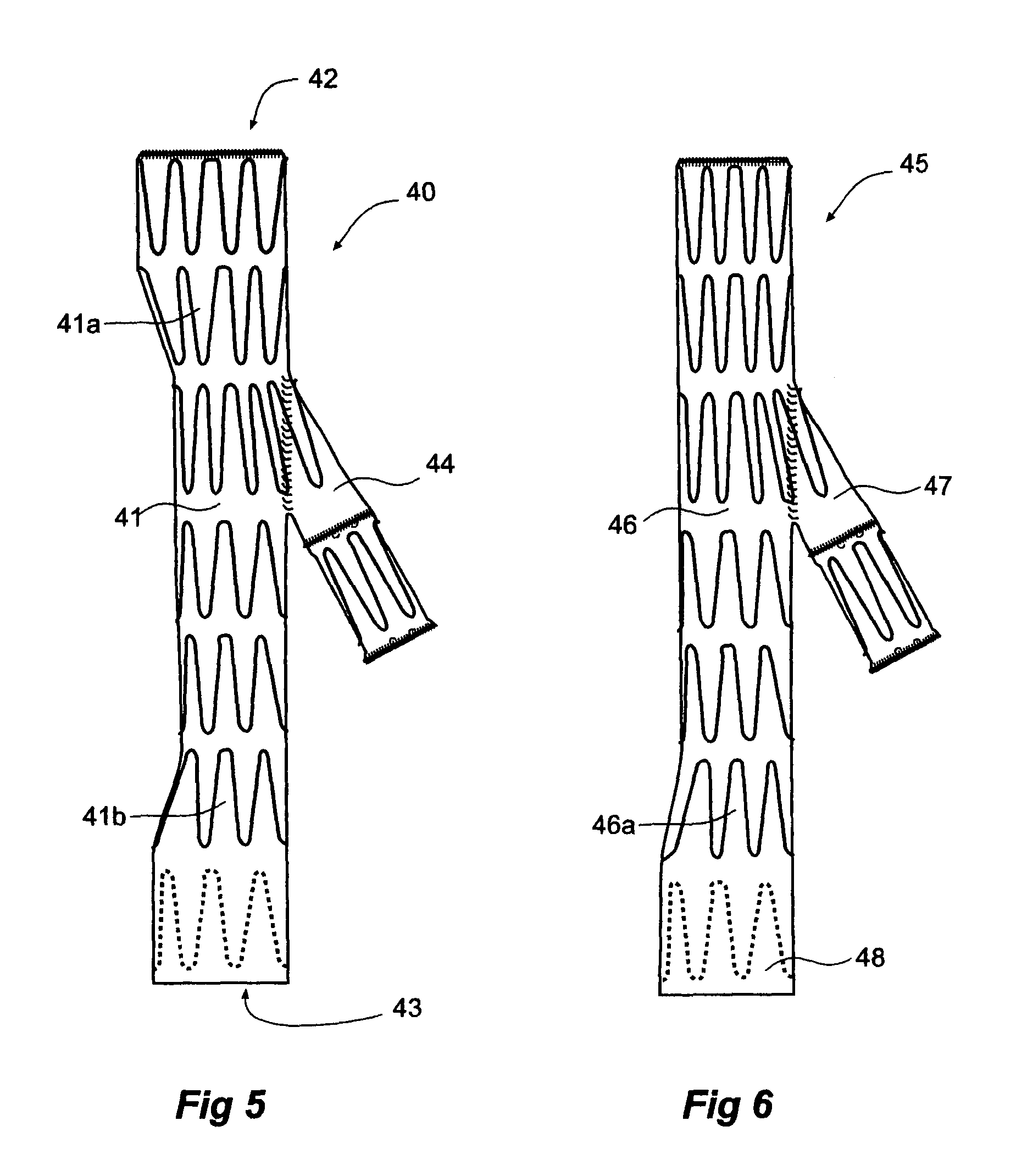
A side branch stent graft (1) suitable for the iliac arteries has a main tubular body (3) of a biocompatible graft material and a tubular side branch (5). The tubular side branch is affixed into the main tubular body so that a side branch lumen is in fluid communication with a main lumen. There is at least one external zig-zag stent (13) on the main tubular body proximal of the tubular side branch, one central external stent (14) which also encompasses the side arm, at least one external zig-zag stent (16) on the main tubular body distal of the tubular side branch and one internal zig-zag stent (15) at the distal end of the main tubular body. A reinforcing ring (9) is around the proximal end of the main tubular body and stitched thereto.

Description

CROSS-REFERENCE TO RELATED APPLICATIONS[0001]This application claims priority of provisional application Ser. No. 60 / 686,252, filed Jun. 1, 2005.TECHNICAL FIELD[0002]This invention relates to a medical device and more particularly to the construction and deployment of a stent graft for the iliac arteryBACKGROUND OF THE INVENTION[0003]The invention will be generally discussed with reference to a branched stent graft which can be deployed so that its branch is directed towards an internal iliac artery from the common iliac but is not so limited and may be used with deployment into any branched vessel but is particularly applicable where the vessel into which the device is deployed is a blind vessel, that is, access is not available from an end of the vessel remote from the bifurcation from a main vessel.[0004]Stent grafts are used for treatment of vasculature in the human or animal body to bypass a repair or defect in the vasculature. For instance, a stent graft may be used to span an...

Claims


Application Information

Patent Timeline
Patent Type & Authority Patents(United States)
IPC IPC(8): A61F2/06
CPCA61F2/07A61F2002/067A61F2002/075A61F2250/0039A61F2/89A61F2220/005A61F2220/0075A61F2002/061
Inventor HARTLEY, DAVID ERNESTIVANCEV, KRASNODAR
Owner COOK MEDICAL TECH LLC
Learn More