Lens barrel and method of operation of lens barrel

a technology of lens barrel and lens barrel, which is applied in the field of lens barrel, can solve the problems of inability to be similarly configured, too large movement of lenses, and inability to achieve zoom drive operation utilizing cam grooves, and achieve the effect of smooth zoom operation and focus operation

Inactive Publication Date: 2010-11-16
NIKON CORP
View PDF12 Cites 6 Cited by
  • Summary
  • Abstract
  • Description
  • Claims
  • Application Information

AI Technical Summary

Benefits of technology

[0007]An object of the present invention is to provide a lens barrel enabling a zoom operation and focus operation smooth even when high powered and a method of operation of a lens barrel.
[0013]Preferably, the barrel is further provided with a vibration reduction system eliminating effects of vibration of the lens barrel, positioned further to an image plane side from the optical system (L2).
[0047]Preferably, the method further comprises eliminating an effect of vibration of the lens barrel further at an image plane side from the optical system (L2).

Problems solved by technology

Conventional lens barrels, in particular lens barrels called “high powered” with zoom powers of over 10× as required for recent lens barrels, have the problems of too large movement of the lenses and the inability to be similarly configured.
Further, if giving priority to the design of the shapes of the focus cam grooves for correcting the amount of feed of the focusing lens accompanying a change in focal distance, the inclined faces of the cam grooves operating at the time of a zoom-operation will end up becoming too sharp and therefore a zoom drive operation utilizing cam grooves will no longer be able to be achieved.

Method used


Image

  • Lens barrel and method of operation of lens barrel
  • Lens barrel and method of operation of lens barrel
  • Lens barrel and method of operation of lens barrel

Examples


Embodiment Construction

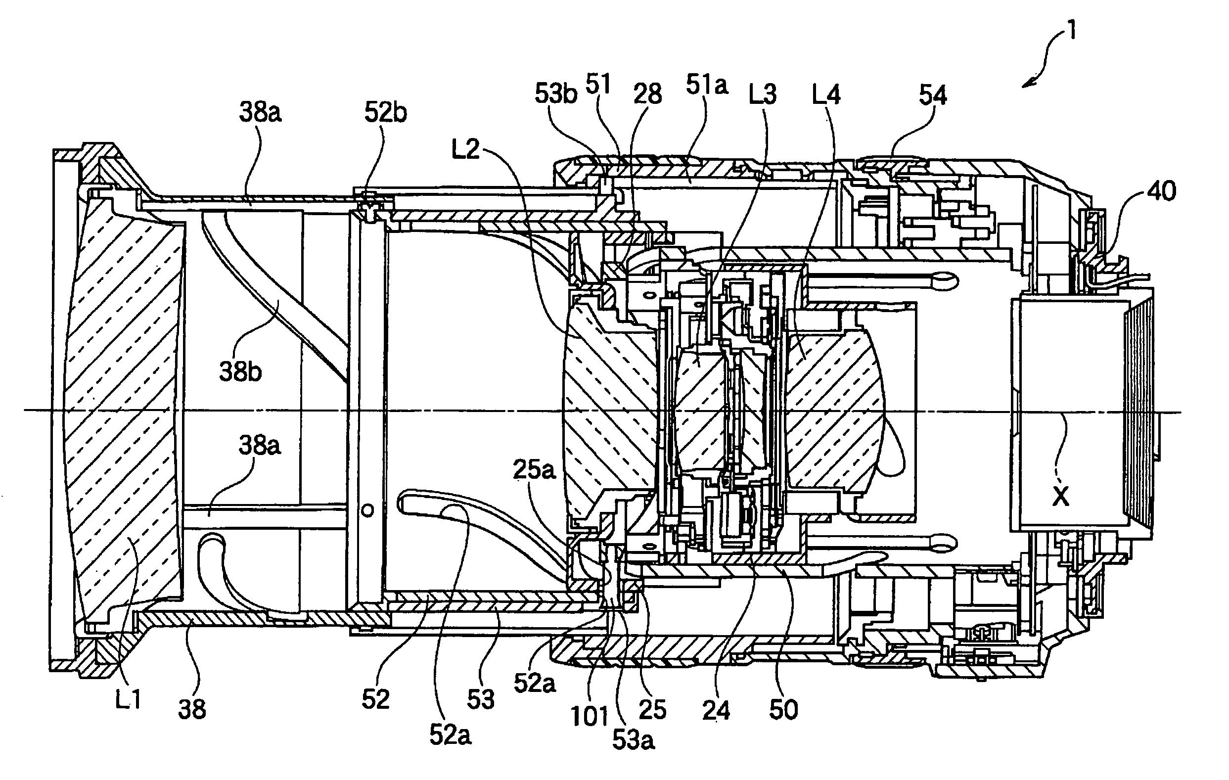
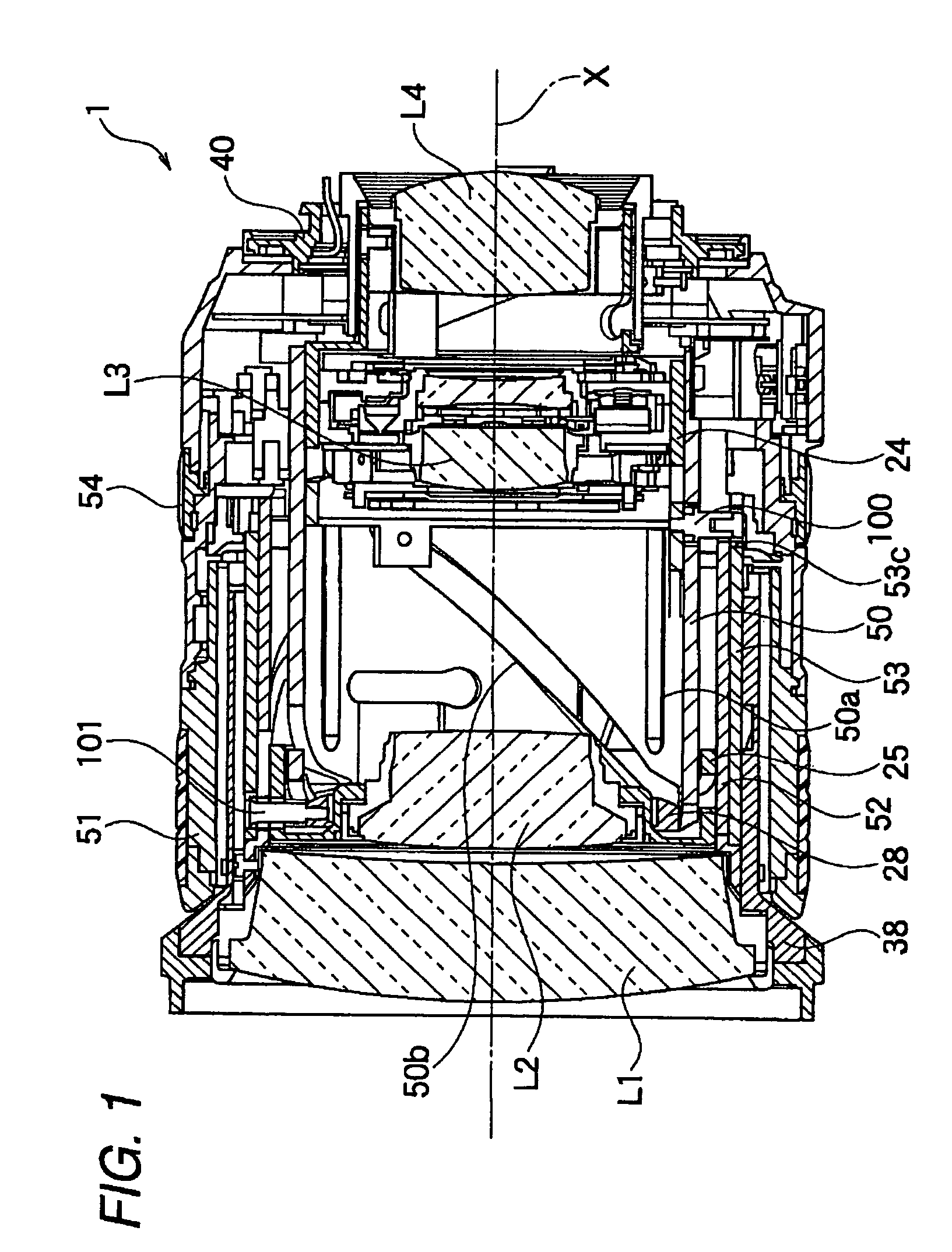
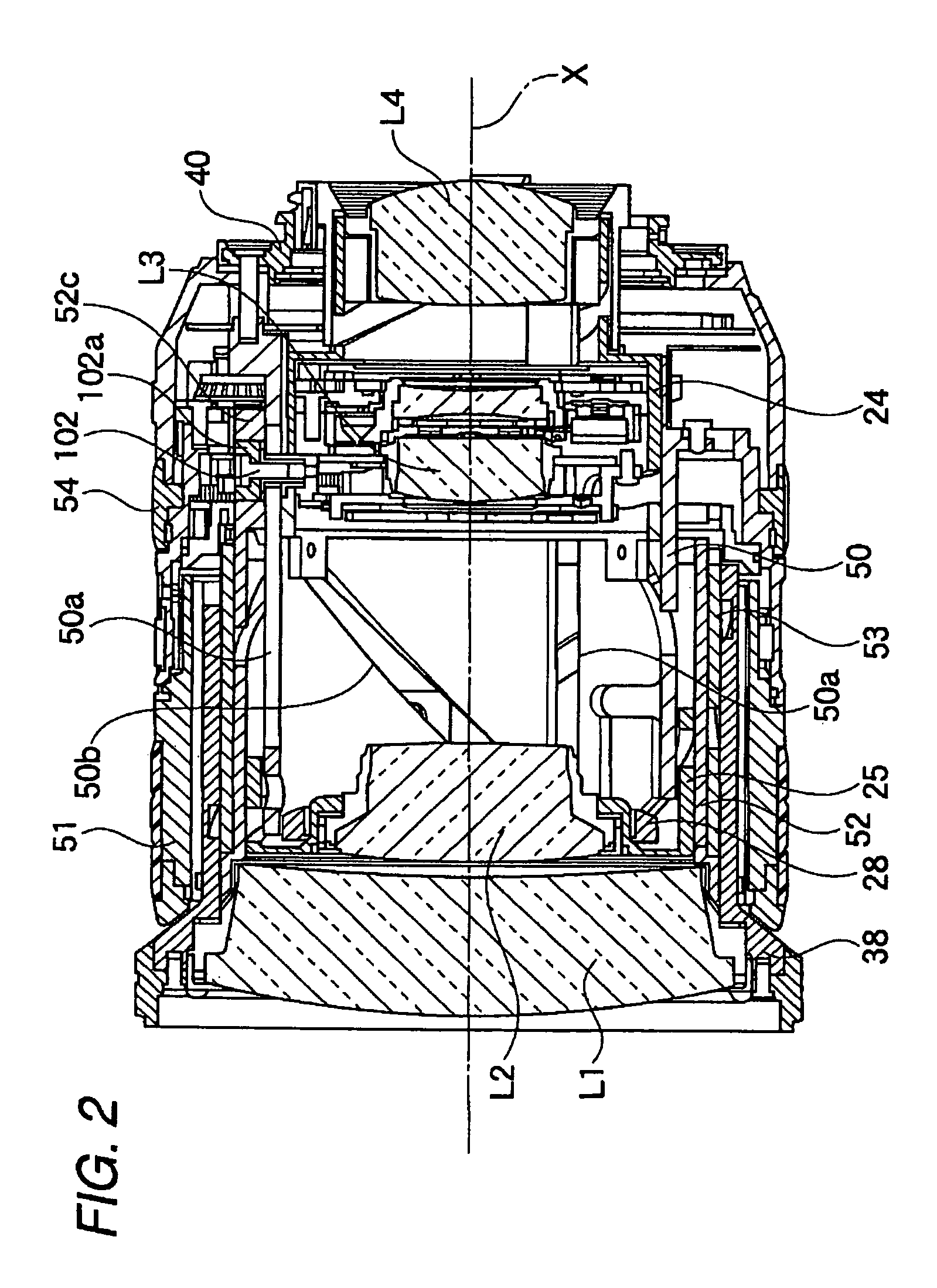
[0083]As shown in FIG. 1 to FIG. 3, the lens barrel 1 in the present embodiment is an exchangeable lens unit having an imaging optical system formed by four lens groups comprised of a first lens group L1, second lens group L2, third lens group L3, and fourth lens group L4 and operating to continuously change the focal distance (zoom operation).

[0084]The first lens group L1 to fourth lens group L4 all engage in independent advancing motion in the optical axis direction due to a zoom operation. The lens barrel 1 in the present embodiment is a lens barrel of the so-called inner focus system. At the time of a focus operation, only the second lens group L2 advances in the optical axis direction. The second lens group L2 corresponds to the focus lens.

[0085]The image capturing optical system of the present embodiment is a lens system changing in the necessary amount of feed of the second lens group L2 at the time of a focus operation in accordance with the zoom position of the imaging opti...


PUM


Abstract

A lens barrel having a first moving barrel, second moving barrel, and a third moving barrel. The first moving barrel has first cam grooves configured corresponding to a focusing operation and holds an optical system used in a focusing operation. The second moving barrel has second cam grooves and is provided in relation to the first moving barrel. The third moving barrel has third cam grooves configured corresponding to a zoom operation and can move relative to a fixed barrel. The second cam grooves correct a position of said optical system corresponding to a drive operation of the third cam grooves.

Description

BACKGROUND OF THE INVENTION[0001]1. Field of the Invention[0002]The present invention relates to a lens barrel enabling a high power zoom operation and a method of operation of a lens barrel.[0003]2. Description of the Related Art[0004]As a prior art, a lens barrel employing an inner focus system and enabling a high power zoom operation is known. As prior art, for example Japanese Patent Publication (A) No. 7-333482 is known.[0005]Conventional lens barrels, in particular lens barrels called “high powered” with zoom powers of over 10× as required for recent lens barrels, have the problems of too large movement of the lenses and the inability to be similarly configured.[0006]Further, if giving priority to the design of the shapes of the focus cam grooves for correcting the amount of feed of the focusing lens accompanying a change in focal distance, the inclined faces of the cam grooves operating at the time of a zoom-operation will end up becoming too sharp and therefore a zoom drive ...

Claims


Application Information

Patent Timeline
Patent Type & Authority Patents(United States)
IPC IPC(8): G02B15/14
CPCG02B7/10G02B15/14G02B15/144
Inventor YAMAZAKI, SATOSHI
Owner NIKON CORP
Why Eureka
Try Eureka