
Fan and fan assembly

a technology of fan and assembly, which is applied in the direction of electrical apparatus casing/cabinet/drawer, instrument, and semiconductor/solid-state device details, etc., can solve the problems of time-consuming and troublesome installation or removal of screws, damage to components,

Inactive Publication Date: 2010-11-02
HON HAI PRECISION IND CO LTD
View PDF11 Cites 12 Cited by
  • Summary
  • Abstract
  • Description
  • Claims
  • Application Information

AI Technical Summary

Benefits of technology

[0004]In a typical computer system, a plurality of fans are secured by screws or the like to a enclosure of the computer system and is used for producing a flow of cooling air over certain electrical components within the enclosure, dissipating heat generated by the closely spaced electrical components so that the components operate within a desired temperature range. However, as computer systems become smaller in size, the components become more tightly arranged within the enclosure of the computer system. When the fans are secured to and / or removed from the enclosure, use of a tool for locking and / or unscrewing screws may cause damage to the components, as there is no enough space for the tool within the enclosure of the computer system. In addition, the installation or removal of the screws is time consuming and troublesome.

Problems solved by technology

When the fans are secured to and / or removed from the enclosure, use of a tool for locking and / or unscrewing screws may cause damage to the components, as there is no enough space for the tool within the enclosure of the computer system.
In addition, the installation or removal of the screws is time consuming and troublesome.

Method used


Image

  • Fan and fan assembly
  • Fan and fan assembly
  • Fan and fan assembly

Examples


Embodiment Construction

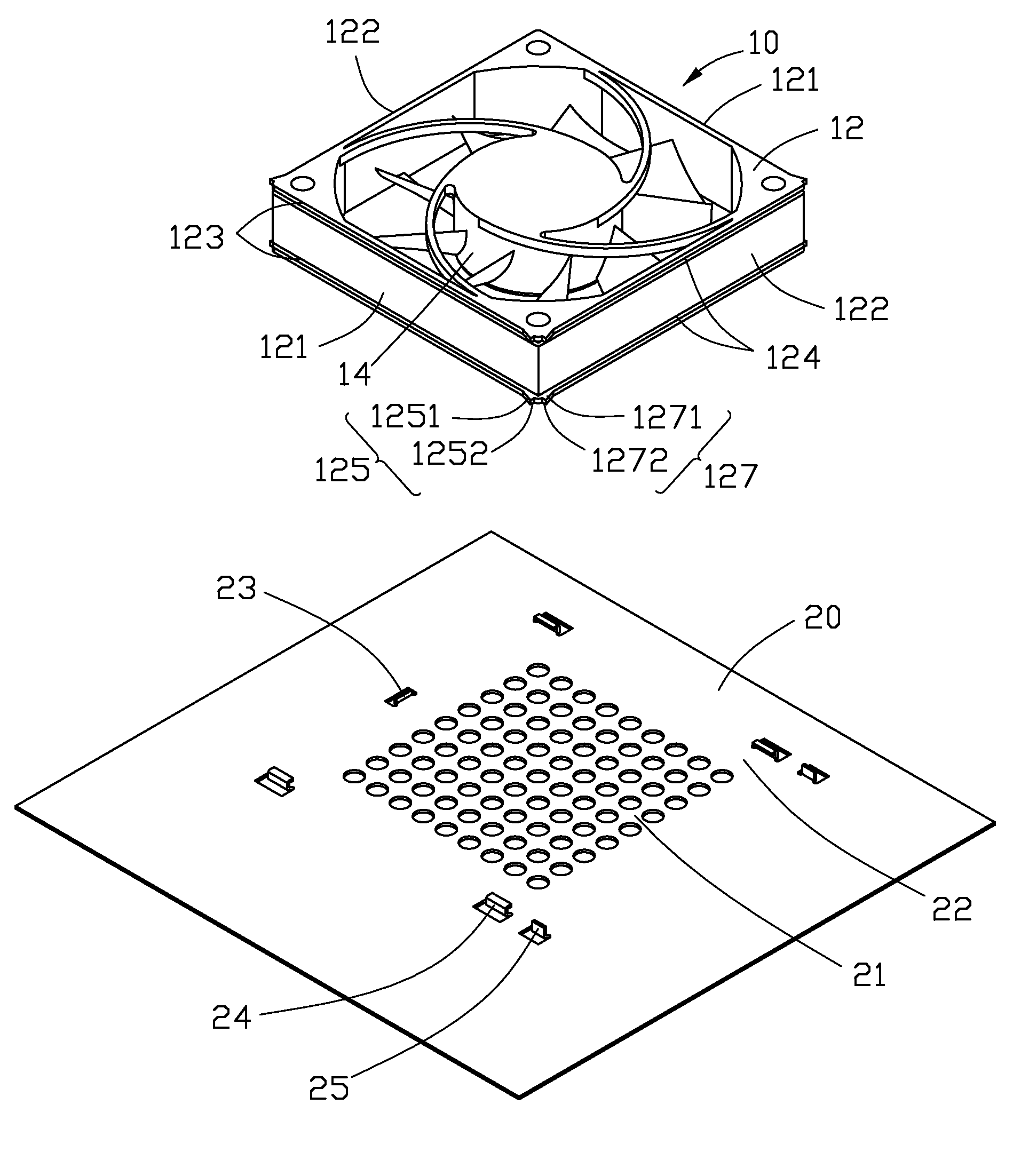
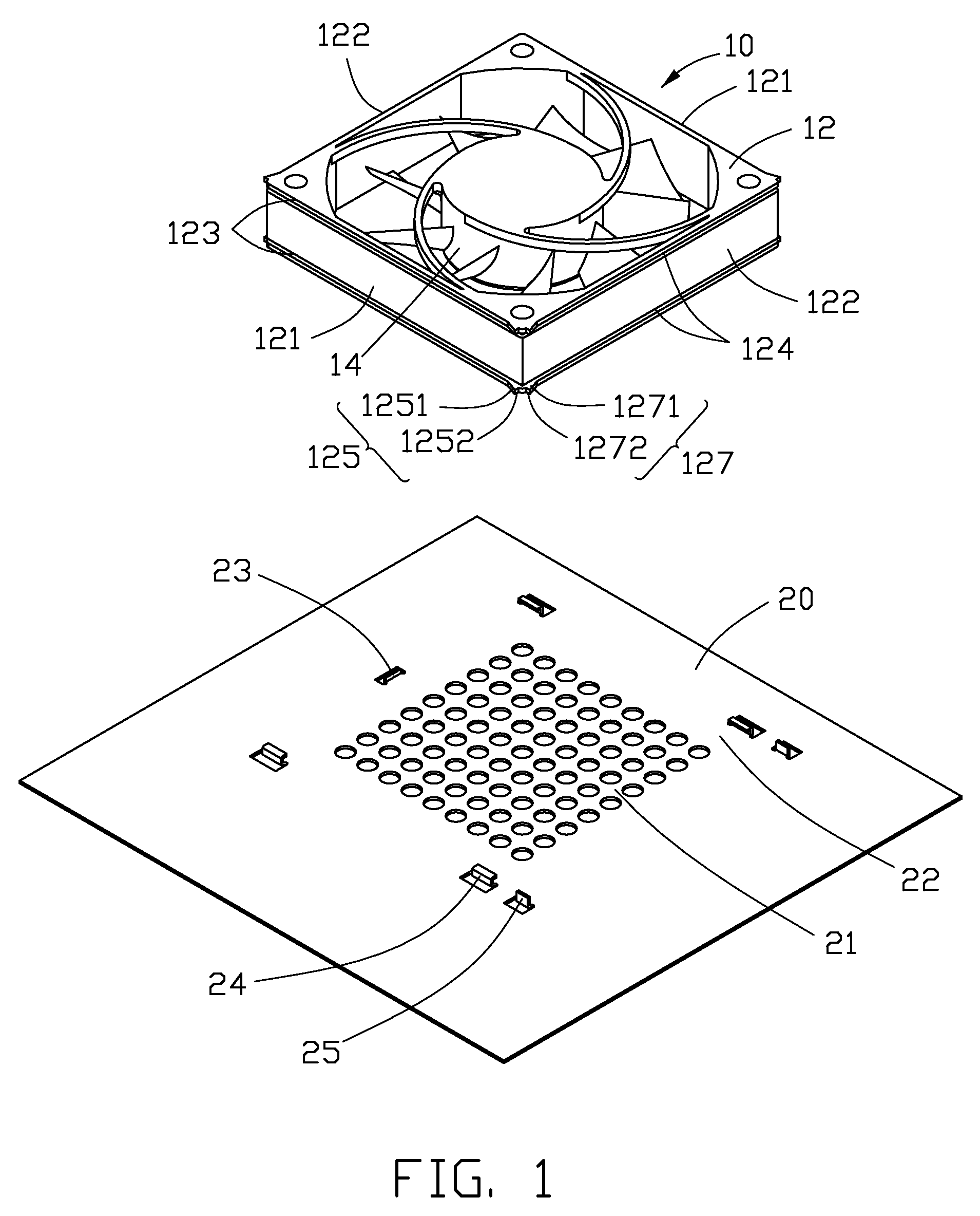
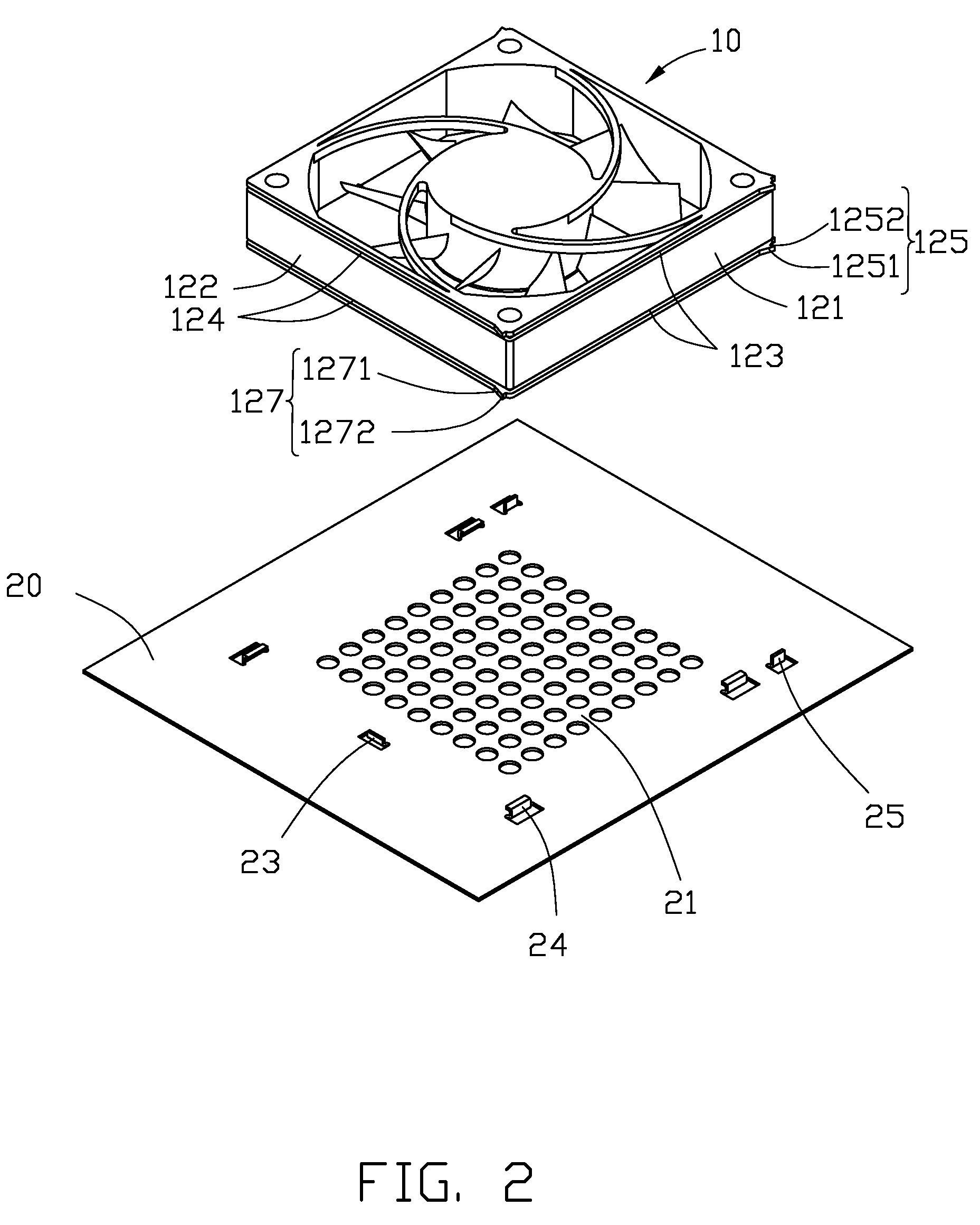
[0009]Referring to FIGS. 1 to 3, an embodiment of a fan 10 includes a fan body 14, and a frame 12 configured for holding the fan body 14 therein. The frame 12 includes two first parallel sidewalls 121, and two second parallel sidewalls 122 perpendicular to the first sidewalls 121. Each of the first sidewalls 121 includes two rims 123 symmetrically extending from bottom and top edges thereof. Each of the second sidewalls 122 includes two rims 124 symmetrically extending from bottom and top edges thereof. Ends of the rims 123 which are directed toward and adjacent to the same second sidewall 122 (that is, the two right ends of the rims 123 in FIG. 1), each include a triangular latch flange 125 extending therefrom perpendicular to the first sidewalls 121. Each of the latch flanges 125 includes a guiding edge 1251 slantingly extending from the rim 123, and a latch edge 1252 perpendicular to the guiding edge 1251. Ends of the rims 124 which are directed toward and adjacent to the same fi...


PUM


Abstract

A fan for easily being attached to a fixing device and includes a fan body and a frame for holding the fan body therein. The frame includes two parallel first sidewalls, and two parallel second sidewalls perpendicular to the first sidewalls. Two pairs of rims symmetrically extend from the first sidewalls and the second sidewalls. Ends of the rims on the first sidewalls toward one same second sidewall each include a latch flange. Ends of the rims on the second sidewalls toward one same first sidewall each includes a latch flange. Each of the latch flanges includes a guiding edge slantingly extending from the corresponding rim, and a latch edge perpendicular to the corresponding rim. Each of the latch flanges includes a guiding edge slantingly extending from the corresponding rim, and a latch edge perpendicular to the corresponding rim.

Description

BACKGROUND[0001]1. Technical Field[0002]The present disclosure relates to heat-dissipating components and, particularly, to a fan and fan assembly.[0003]2. Description of Related Art[0004]In a typical computer system, a plurality of fans are secured by screws or the like to a enclosure of the computer system and is used for producing a flow of cooling air over certain electrical components within the enclosure, dissipating heat generated by the closely spaced electrical components so that the components operate within a desired temperature range. However, as computer systems become smaller in size, the components become more tightly arranged within the enclosure of the computer system. When the fans are secured to and / or removed from the enclosure, use of a tool for locking and / or unscrewing screws may cause damage to the components, as there is no enough space for the tool within the enclosure of the computer system. In addition, the installation or removal of the screws is time co...

Claims


Application Information

Patent Timeline
Patent Type & Authority Patents(United States)
IPC IPC(8): H05K7/20
CPCG06F1/20
Inventor SUN, ZHENG-HENG
Owner HON HAI PRECISION IND CO LTD
Learn More