
Folding utility knife

a utility knife and folding technology, applied in the field of utility knives, can solve the problems of blade being accidentally removed or dislodged during use, blade being difficult to use, and requiring tools to release the blade mechanism,

Active Publication Date: 2010-10-19
BLACK & DECKER INC
View PDF94 Cites 70 Cited by
  • Summary
  • Abstract
  • Description
  • Claims
  • Application Information

AI Technical Summary

Benefits of technology

The present invention is a folding utility knife with a blade holder that can be opened and closed. The blade holder has a blade engaging portion that can be moved between a locked position, a cutting position, and a blade release position. The knife also has a locking member that can be moved between a blade locking position and a blade release position. A first biasing member is used to move the blade release actuator between the locked and cutting positions, and a second biasing member is used to move the locking member between the blade locking and blade release positions. The blade holder has a recess that exposes a segment of the blade for cutting objects, and the blade holder has an upper surface with a first and second upper surface portion, where the second upper surface portion is inclined at an acute angle relative to the first upper surface portion. The technical effects of the invention include improved functionality, durability, and ease of use.

Problems solved by technology

One drawback of such prior art utility knives is that the blade is allowed to be removed from the blade holder when in the operational position, and as a result, the blade can become accidentally removed or dislodged during use.
Another drawback of some prior art folding utility knives is that the blade release mechanisms require tools, or otherwise are not convenient to use.

Method used


Image

  • Folding utility knife
  • Folding utility knife
  • Folding utility knife

Examples


Embodiment Construction

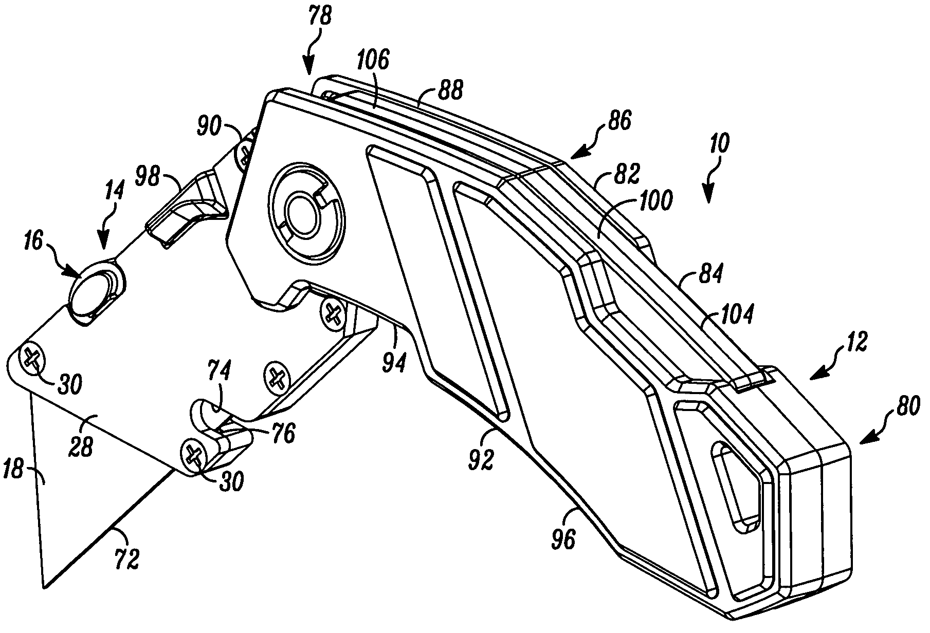
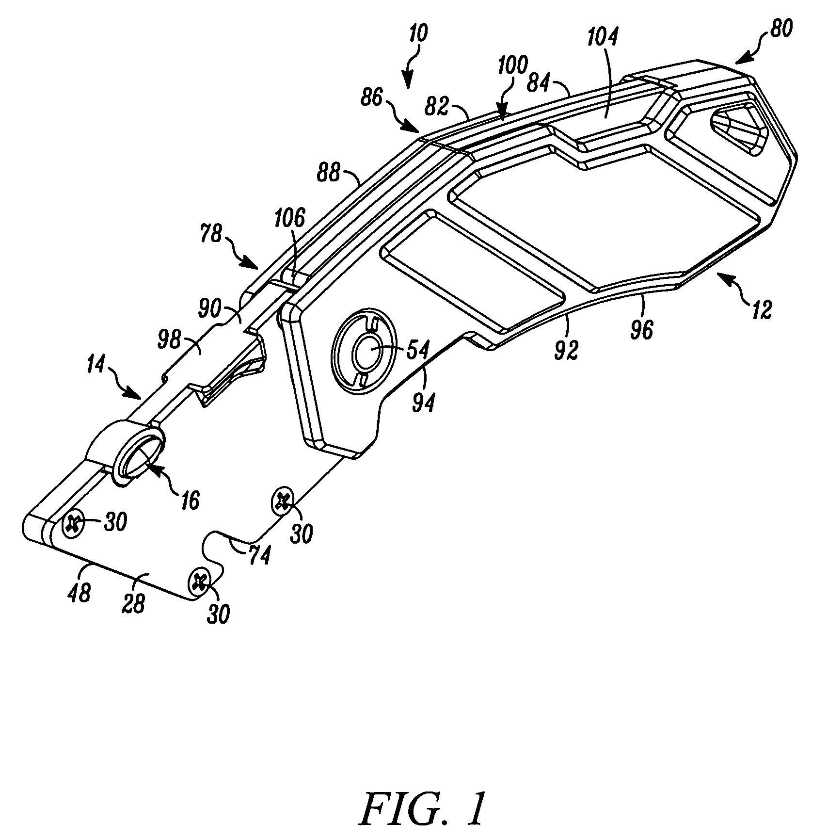
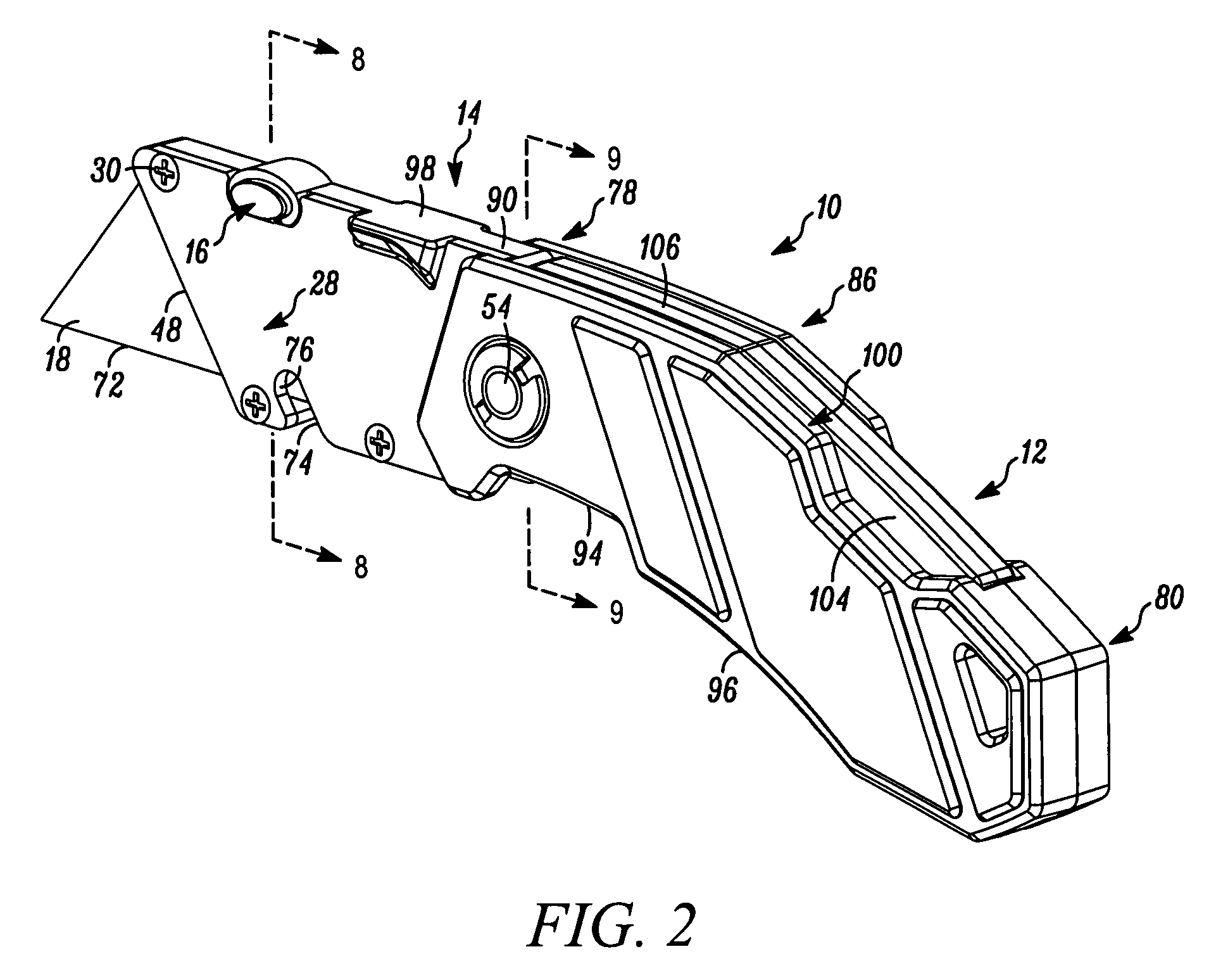
[0045]In FIG. 1 a folding utility knife embodying the present invention is indicated generally by the reference numeral 10. The folding utility knife 10 comprises a handle 12 and a blade holder 14 pivotally mounted on the handle. The blade holder 14 is movable between (i) a closed position with the blade holder pivoted inwardly toward the handle (FIG. 4), (ii) a cutting position with the blade holder pivoted outwardly relative to the handle (FIG. 2), and (iii) a blade release position located between the closed position and the cutting position for releasing a utility knife blade from the blade holder (FIG. 3). The folding utility knife 10 further comprises a blade release actuator 16 located on the blade holder 14. As indicated by the arrow in FIG. 8, the blade release actuator 16 is movable between (i) a first position with the blade release actuator 16 extending outwardly of the blade holder 14 and preventing release of a utility knife blade 18 located on the blade holder (FIG. 8...


PUM


Abstract

A folding utility knife has a handle and a blade holder pivotally mounted on he handle. The blade holder is movable between (i) a closed position with the blade holder pivoted inwardly toward the handle, (ii) a cutting position with the blade holder pivoted outwardly relative to the handle, and (iii) a blade release position located between the closed position and the cutting position. A blade release actuator is located on the blade holder and is movable between (i) a first position preventing release of a utility knife blade located on the blade holder, and (ii) a second position permitting release of a utility knife blade located on the blade holder. A locking member is movable between (i) a blade locking position with the blade holder located in the cutting position that prevents movement of the blade release actuator from the first position to the second position, and (ii) a blade release position with the blade holder located in the blade release position that permits movement of the blade release actuator from the first position to the second position to, in turn, release a utility knife blade from the blade holder.

Description

FIELD OF THE INVENTION[0001]The present invention relates to utility knives, and more particularly, to folding utility knives.BACKGROUND INFORMATION[0002]Folding utility knives typically include a handle and a blade holder pivotally mounted to the handle. The blade holder holds a utility knife blade, such as a trapezoidal utility knife blade. Part of the utility knife blade is enclosed within the blade holder, and another part of the blade extends outwardly of the blade holder with the cutting edge exposed for use. The blade holder typically includes a mechanism for securing the blade to the blade holder, such as a fastener or other type of blade securing and releasing mechanism. The blade holder is movable between a closed position pivoted inwardly toward the handle with the exposed cutting edge of the blade received within the handle, and an open position pivoted outwardly away from the handle with the cutting edge of the blade exposed for use. The blade is removed and either flip...

Claims


Application Information

Patent Timeline
Patent Type & Authority Patents(United States)
IPC IPC(8): B26B1/02
CPCB26B1/042B26B5/00B26B3/06
Inventor LEBLANC, NORMANLEVINE, STEVEN R.LEYDEN, CHRISTIAN S.
Owner BLACK & DECKER INC
Learn More