Centralised lubrication of large diesel engines

a technology for diesel engines and lubrication, applied in the direction of engine lubrication, pressure lubrication, electrical control, etc., can solve the problem of limit the possibility of user control of injection tim

Inactive Publication Date: 2010-10-05
HANS JENSEN LUBRICATORS
View PDF13 Cites 4 Cited by
  • Summary
  • Abstract
  • Description
  • Claims
  • Application Information

AI Technical Summary

Benefits of technology

[0032]A system according to the invention may be based on standard components. This is advantageous, as hereby it is possible to perform a relatively simple rebuilding of existing lubricating systems in order to achieve the advantages of the present invention. By and large, it is possible to keep lubrication apparatuses in their present design, which of course would be a significant advantage. It is only required to provide a drive motor and a control therefor which can co-ordinate rotation of the control shaft with the position of the crankshaft / piston of the diesel engine.

Problems solved by technology

With the mechanical coupling, there is a limitation in the possibilities of the user for controlling the injection time only for synchronised lubrication which is timed according to the rotation of the crankshaft.
This is e.g. the case with pre-lubricating the cylinders, where the user has the possibility of interfering by providing a cylinder lubrication before starting the engine, and thereby before the rotation of the crankshaft has started.

Method used


Image

  • Centralised lubrication of large diesel engines
  • Centralised lubrication of large diesel engines
  • Centralised lubrication of large diesel engines

Examples


Embodiment Construction

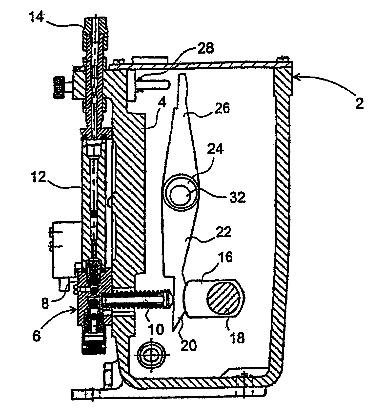
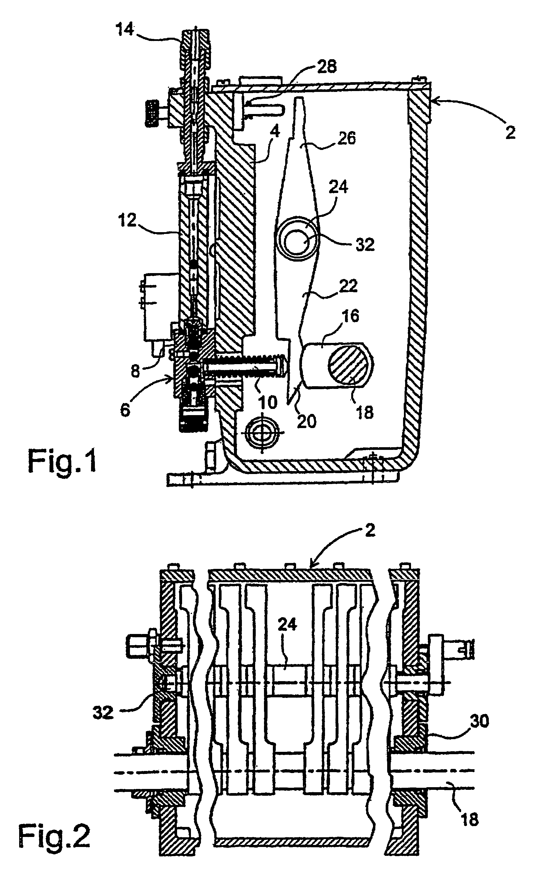
[0052]The apparatus shown in FIGS. 1 and 2 has a box-shaped apparatus housing 2 which on a front wall 4 carries a row of reciprocating pump units 6, of which only one is shown in FIG. 1. The unit has a valve housing 8 with a lower inlet for lubricating oil, an intermediate section for accommodating a piston 10 protruding into the apparatus housing 2 and an upper outlet for reciprocating pump thus formed. The outlet is connected to an upper connector 14 via a flow indicator 12, and from the whole row of these connectors connecting pipes emanate to the lubrication points on the associated engine cylinder, e.g. in a number of 6-24.

[0053]The pistons 10 are actuated for pressing in by means of actuation cams 16 on a through-going control shaft 18 which is rotated synchronously with the crankshaft of the engine, and which is seated in bearing cases 30. The pistons are not actuated directly, but via thrust pads 20 on respective rocker arms 22 which are pivoting about a fixed journal 24 wit...


PUM


Abstract

A centralised lubrication system and method lubricates cylinder faces in large diesel engines, particularly marine engines. At least one lubricating apparatus has a rotating control shaft preferably running synchronously with the engine main shaft. To make a system that does not have a mechanical drive between the lubricating apparatus and the main shaft, the system is constructed with an AC motor driving the control shaft. Reference means are provided in association with the main shaft, indicating the angular position of the main shaft, and sensor means detect the position of the reference means. The system includes a control unit receiving signals from the sensor and detecting angular position as well as angular speed of the reference means and the main shaft. The control unit is connected with and controls the AC motor (36) for regulating the rotation of the control shaft (18) and thereby actuation of reciprocating pumps providing the cylinder lubrication.

Description

[0001]This application claims the benefit of Danish Application No. PA 2003 01582 filed Oct. 28, 2003 and PCT / DK2004 / 000745 filed Oct. 28, 2004, which are hereby incorporated by reference in their entirety.BACKGROUND OF THE INVENTION[0002]The present invention concerns a centralised lubrication system for lubricating the cylinder faces in large diesel engines, particularly marine engines, including at least one lubricating apparatus with a number of reciprocating pumps actuated by cams on a rotating control shaft which is driven preferably synchronously with the main shaft of the diesel engine.[0003]Furthermore, the present invention concerns a method for lubricating the cylinder faces in large diesel engines, particularly marine engines, including at least one lubricating apparatus with a number of reciprocating pumps actuated by cams on a rotating control shaft which is driven preferably synchronously with the main shaft of the diesel engine.[0004]The lubricating apparatuses are t...

Claims


Application Information

Patent Timeline
IPC IPC(8): F01M1/14F01M1/08F16N7/38F01M1/02F01M3/04F02D41/34
CPCF01M1/14F01M2001/083F02D41/009F02D41/0097F01M1/02F01M3/04F16N7/38
Inventor NIELSEN, IB HELMER
Owner HANS JENSEN LUBRICATORS
Why Eureka
Try Eureka