
Embedment device for fiber reinforced structural cementitious panel production

a technology of embedding device and fiber reinforced structural, which is applied in the direction of application, manufacturing tools, drawing profiling tools, etc., can solve the problems of increasing the production cost of cementitious panels, poor panel strength development, and low panel strength, and achieve the effect of reducing the downtime of the board lin

Active Publication Date: 2010-09-14
UNITED STATES GYPSUM CO
View PDF33 Cites 17 Cited by
  • Summary
  • Abstract
  • Description
  • Claims
  • Application Information

AI Technical Summary

Benefits of technology

The present invention is a device used in a cementitious panel production line to embed fibers into a slurry. The device includes a wire grid or honeycomb structure that is moved vertically up and down into the slurry to press it together and embed the fibers. The movement creates a "kneading" or "massaging" action in the slurry, which prevents the buildup of slurry on the grid and reduces downtime due to premature setting of clumps of slurry. The device can be moved up and down by a piston or can be run pneumatically, hydraulically, or manually. The technical effect of the invention is to improve the production efficiency and quality of cementitious panels.

Problems solved by technology

Due to non-uniform distribution the reinforcing properties resulting due to the fiber-matrix interaction vary through the thickness of the board, depending on the thickness of each board layer.
When insufficient penetration of the slurry through the fiber network occurs, poor bonding between the fibers and the matrix results, causing low panel strength.
Also, in some cases when distinct layering of slurry and fibers occurs, improper bonding and inefficient distribution of fibers causes poor panel strength development.
Also, production line downtime, caused by premature setting of the slurry, especially in particles or clumps which impair the appearance of the resulting board, increases cementitious panel production costs, causes structural weaknesses and interferes with production equipment efficiency.
Significant buildups of prematurely set slurry on production equipment require shutdowns of the production line, thus increasing the ultimate board cost.

Method used


Image

  • Embedment device for fiber reinforced structural cementitious panel production
  • Embedment device for fiber reinforced structural cementitious panel production
  • Embedment device for fiber reinforced structural cementitious panel production

Examples


Embodiment Construction

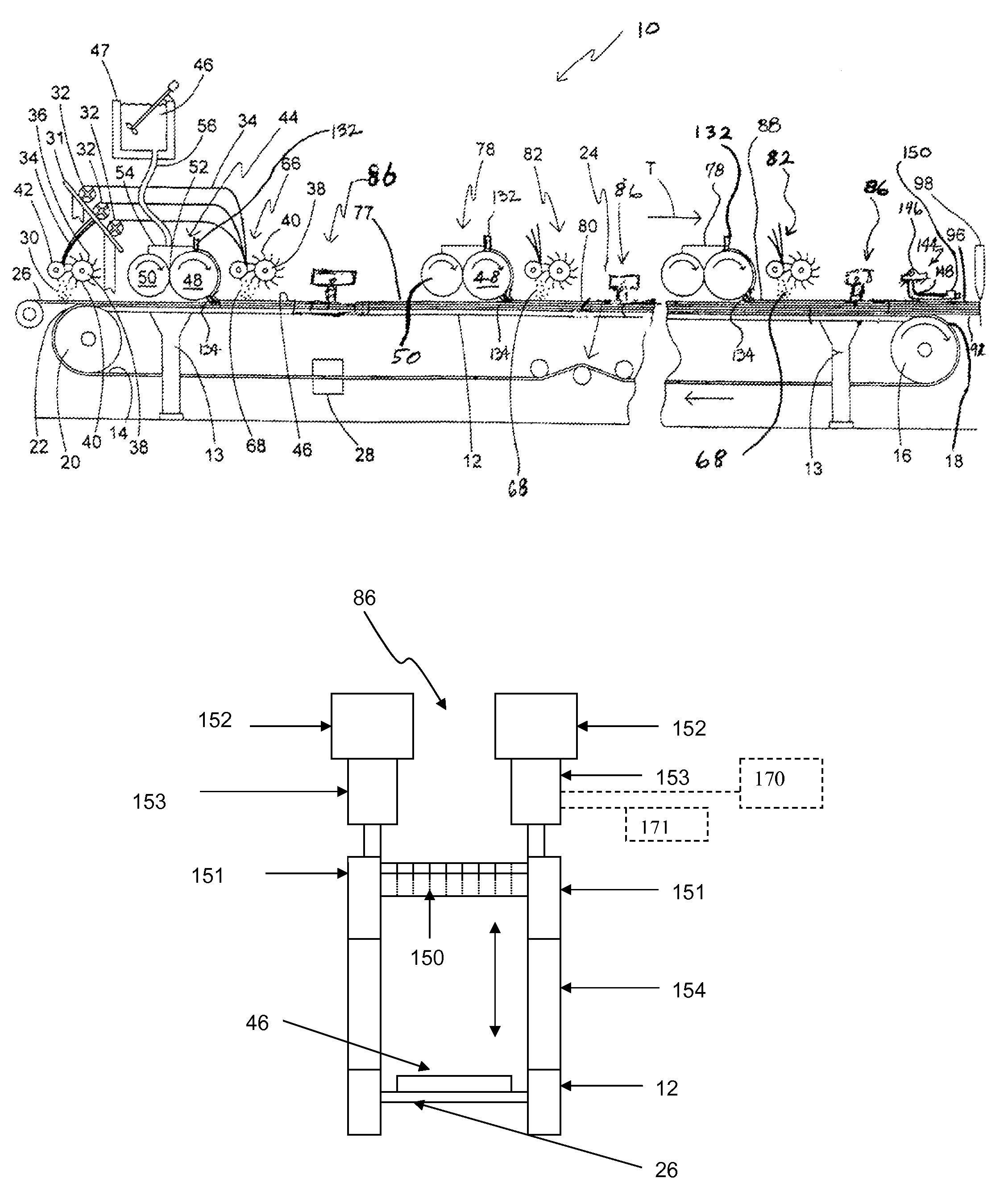
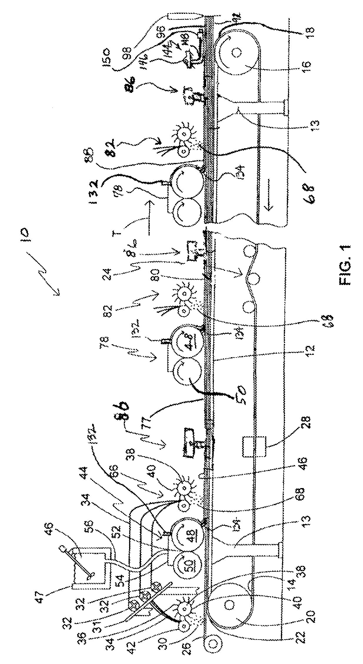
[0034]Referring now to FIG. 1, a cementitious panel production line is diagrammatically shown and is generally designated 10. The production line 10 includes a support frame or forming table 12 having a plurality of legs 13 or other supports. Included on the support frame 12 is a moving carrier 14, such as an endless rubber-like conveyor belt with a smooth, water-impervious surface, however porous surfaces are contemplated. As is well known in the art, the support frame 12 may be made of at least one table-like segment, which may include designated legs 13 or other support structure. The support frame 12 also includes a main drive roll 16 at a distal end 18 of the frame, and an idler roll 20 at a proximal end 22 of the frame. Also, at least one belt tracking and / or tensioning device 24 is typically provided for maintaining a desired tension and positioning of the carrier 14 upon the rolls 16, 20. In this embodiment, the SCP panels are produced continuously as the moving carrier proc...


PUM

PropertyMeasurementUnit
sizeaaaaaaaaaa
diameteraaaaaaaaaa
diameteraaaaaaaaaa

Abstract

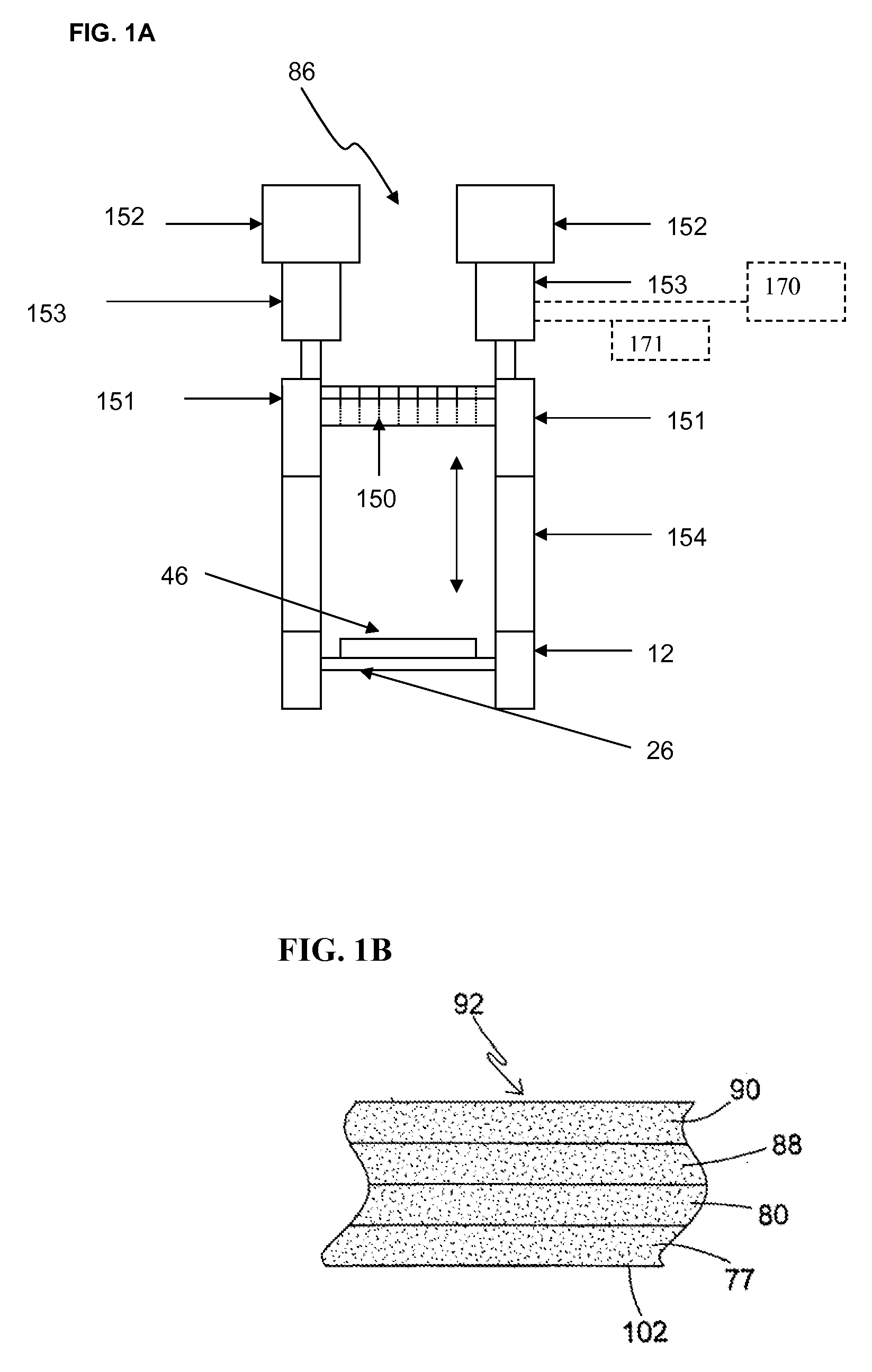
An embedment device for use in a cementitious panel production line such as a structural cementitious panel (SCP) production line wherein hydraulic cement slurry is transported on a moving web on a support frame, and chopped fibers are deposited upon the slurry. The device includes as one embodiment, a wire grid structure mounted on a reciprocating shaft driven by a piston which moves the grid down into the slurry and then up out of the slurry transverse of the travel of the slurry layer on the web. An alternative embodiment device includes a grid cell structure with thin walls extending upward from the grid surface in contact with the slurry that is moved up and down in a reciprocating motion transverse of the travel of the slurry layer on the web. The intermeshing relationship of the grid cell with the fiber and slurry enhances embedment of the fibers into the slurry and also prevents clogging of the device by fibers and prematurely set slurry particles.

Description

CROSS REFERENCE TO RELATED APPLICATIONS[0001]This application is related to co-pending patent applications:[0002]U.S. Pat. No. 6,986,812 entitled SLURRY FEED APPARATUS FOR FIBER-REINFORCED STRUCTURAL CEMENTITIOUS PANEL PRODUCTION, issued on Jan. 17, 2006;[0003]U.S. application Ser. No. 10 / 666,294, now U.S. Pat. No. 7,445,738, entitled APPARATUS FOR PRODUCING HIGH STRENGTH FIBER-REINFORCED STRUCTURAL CEMENTITIOUS PANELS, filed Sep. 18, 2003;[0004]U.S. application Ser. No. 11 / 555,647, entitled PROCESS AND APPARATUS FOR FEEDING CEMENTITIOUS SLURRY FOR FIBER-REINFORCED STRUCTURAL CEMENT PANELS, filed Nov. 1, 2006;[0005]U.S. application Ser. No. 11 / 555,655, now U.S. Pat. No. 7,524,386, entitled METHOD FOR WET MIXING CEMENTITIOUS SLURRY FOR FIBER-REINFORCED STRUCTURAL CEMENT PANELS, filed Nov. 1, 2006;[0006]U.S. application Ser. No. 11 / 555,661, entitled PANEL SMOOTHING PROCESS AND APPARATUS FOR FORMING A SMOOTH CONTINUOUS SURFACE ON FIBER-REINFORCED STRUCTURAL CEMENT PANELS, filed Nov. 1,...

Claims


Application Information

Patent Timeline
Patent Type & Authority Patents(United States)
IPC IPC(8): B28B1/26
CPCB28B1/522B28B5/027B28B23/0062B28C5/34B28C5/40
Inventor DUBEY, ASHISH
Owner UNITED STATES GYPSUM CO
Learn More