Installation and withdrawal apparatus

a technology of which is applied in the direction of electrical apparatus construction details, coupling device connections, support structure mounting, etc., can solve the problems of unintentional change of the position unintended change of the installation and removal handle, etc., and achieves cost-favorable manufacturing, simple operation, and simple and space-saving design of the holding apparatus

Inactive Publication Date: 2010-09-07
ELMA ELECTRONIC
View PDF8 Cites 0 Cited by
  • Summary
  • Abstract
  • Description
  • Claims
  • Application Information

AI Technical Summary

Benefits of technology

[0004]It is an object of the present invention to provide an installation and withdrawal apparatus for the plugging in and removing of a plug-in assembly into or out of an assembly support which is protected against unintended inward pivoting, has a simple operation and can be manufactured economically favorably in comparison with installation and withdrawal apparatuses of the prior art.
[0011]The installation and withdrawal apparatus has the advantage that it is held in the outwardly pivoted position by the first holding apparatus such that an unintentional inward pivoting is avoided on the movement of the plug-in assembly and the inward pivoting of the installation and withdrawal handles is only possible against noticeable resistance. If a leg spring is used as the holding element, its spring force has the effect that the installation and withdrawal apparatus is pivoted into the outwardly pivoted position as soon as the plug-in assembly is removed from the assembly support. The arrangement of the first holding element in the region of the bearing element permits a simple and space-saving design of the holding apparatus and a cost-favorable manufacture of the installation and withdrawal apparatus. A further advantage of the installation and withdrawal apparatus in accordance with the invention is the simple operation thereof. Only the resistance of the holding apparatus has to be overcome for the inward pivoting of the installation and withdrawing handle.

Problems solved by technology

The installation and withdrawal handles must be fully pivoted out for the plugging in of a plug-in assembly as they otherwise impede the plugging in of the plug-in assembly into the assembly support or make it absolutely impossible.
The position of the installation and removal handles can change unintentionally on a direct contact or on a more powerful movement of the plug-in assembly without appropriate precautions.
In particular the upper installation and withdrawal handle tends to tilt downwardly due to gravity so that it has to be held tight on the plugging in of the plug-in assembly.
The problem arises with such installation and withdrawal handles of unintended inward pivoting to a special degree.
This design is relatively complex.
The lever pulling handle can also only be inwardly pivoted by simultaneously actuating the blocking lever, which complicates the operation.

Method used


Image

  • Installation and withdrawal apparatus
  • Installation and withdrawal apparatus
  • Installation and withdrawal apparatus

Examples


Embodiment Construction

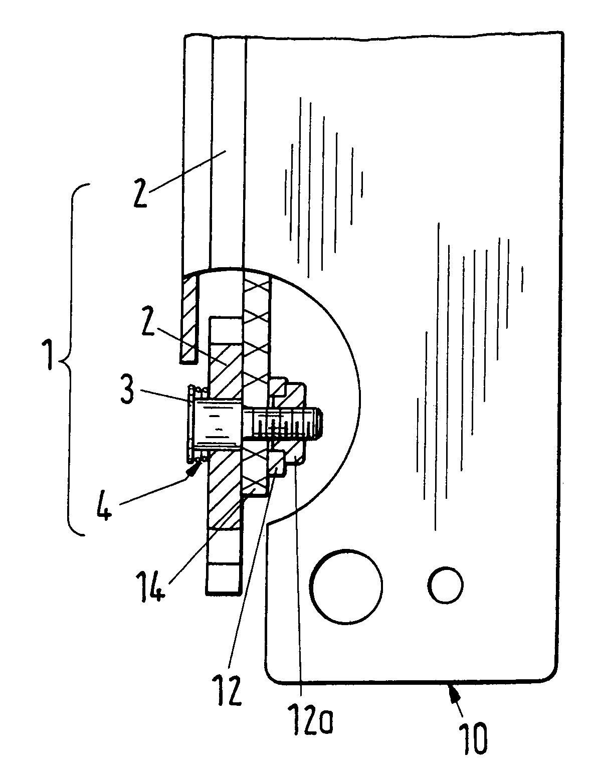
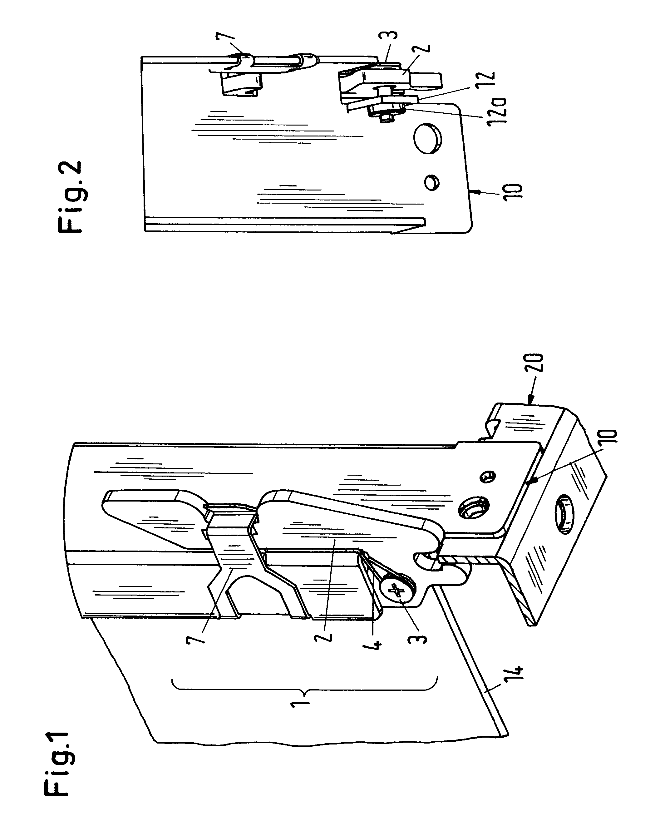
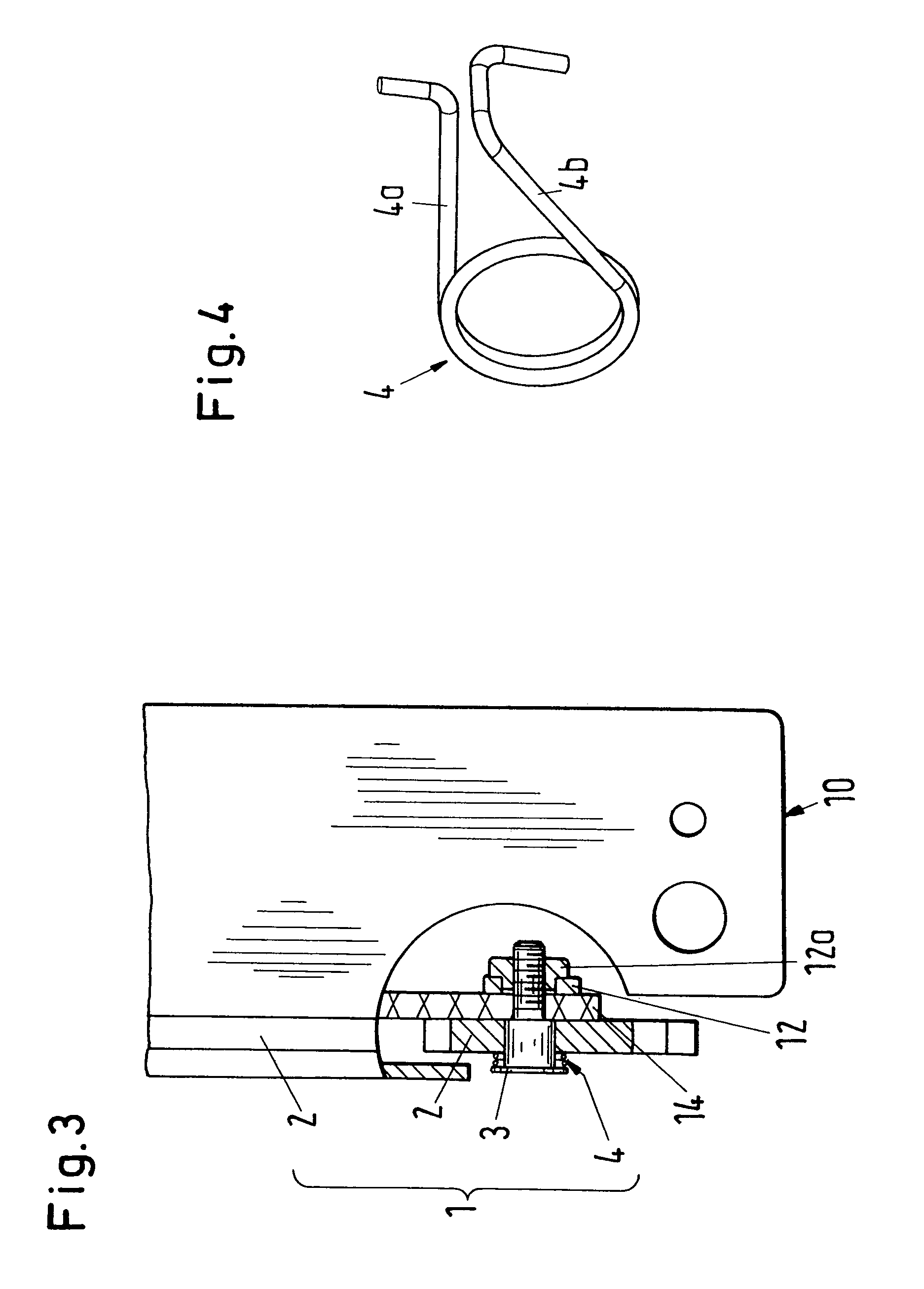
[0021]FIG. 1 shows an oblique view of a section of a plug-in assembly with an embodiment of an installation and withdrawal apparatus 1 in accordance with the present invention. The installation and withdrawal apparatus includes an installation and withdrawal handle 2 and a bearing element 3 about which the installation and withdrawal handle is rotatable and which can be made, for example, as a fitting shoulder screw or as a screw with a sleeve. The installation and withdrawal apparatus 1 further includes a holding apparatus having at least one holding element 4 which is formed as a leg spring in the embodiment shown in FIG. 1, the leg spring being arranged in the region of the bearing element 3 and surrounding it, for example.

[0022]Furthermore, in the section shown in FIG. 1, a front structure 10 and a printed-circuit board 14 of a plug-in assembly are shown as well as a front structure 20 of an assembly support into which the plug-in assembly has been inserted. The installation and...


PUM


Abstract

An installation and withdrawal apparatus (1) for the plugging in and withdrawal of a plug-in assembly into or out of an assembly support includes an installation and withdrawal handle (2) and a bearing element (3) about which the installation and withdrawal handle (2) can be rotated. The installation and withdrawal apparatus (1) further includes a holding element (4) to hold the installation and withdrawal handle (2) in a position suitable for plugging in the plug-in assembly, with the holding element (4) being arranged on the bearing element (3).

Description

BACKGROUND OF THE INVENTION[0001]The invention relates to an installation and withdrawal apparatus for the plugging in and removal of a plug-in assembly into or out of an assembly support as well as to a plug-in assembly having such an installation and withdrawal apparatus and to an assembly support having such a plug-in assembly.[0002]Plug-in assemblies introducible into assembly supports have multiple plug connections on the rear side whose plug-in and removal forces have to be overcome on the plugging in or removal of the plug-in assembly. Plug-in assemblies are therefore usually provided with a lower and / or an upper installation and withdrawal handle in order to facilitate the plugging in and the removal. The installation and withdrawal handles are arranged rotatably and are supported at a structure of the assembly support at the front side such that the installation and withdrawal handles act as levers on the plugging in and removal. The installation and withdrawal handles must...

Claims


Application Information

Patent Timeline
Patent Type & Authority Patents(United States)
IPC IPC(8): H05K7/18F16B1/00H01R13/44H01R13/629H05KH05K7/10H05K7/14
CPCH05K7/1409H01R13/62933
Inventor HEUSSI, GEORG
Owner ELMA ELECTRONIC
Why Eureka
Try Eureka