
Insulation displacement connector

Inactive Publication Date: 2010-09-07
POWER PROD
View PDF14 Cites 18 Cited by
  • Summary
  • Abstract
  • Description
  • Claims
  • Application Information

AI Technical Summary

Problems solved by technology

However, forming such connections commonly require that a crimping tool be used to force the blade into the wire insulation.

Method used


Image

  • Insulation displacement connector
  • Insulation displacement connector
  • Insulation displacement connector

Examples


Embodiment Construction

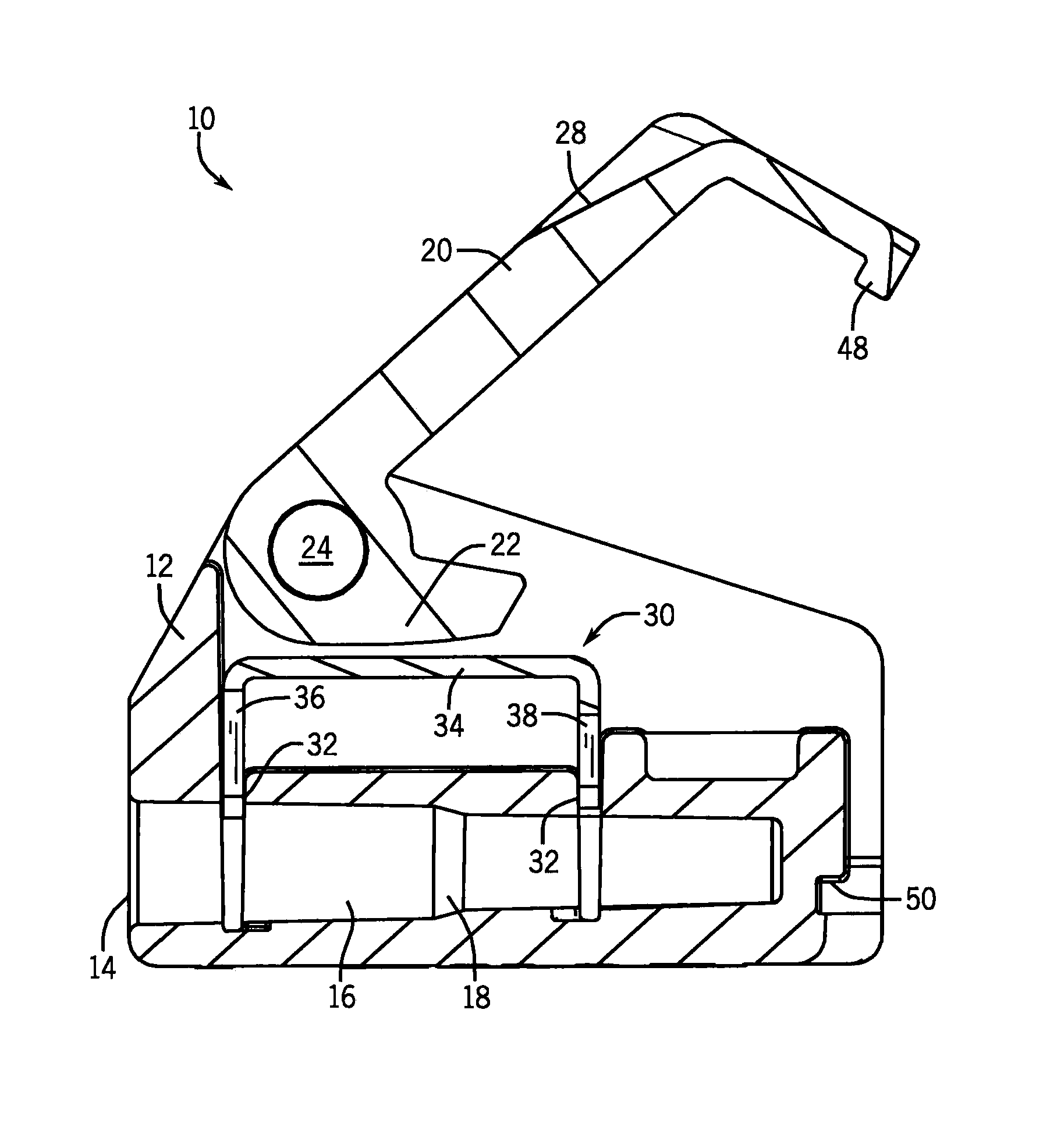
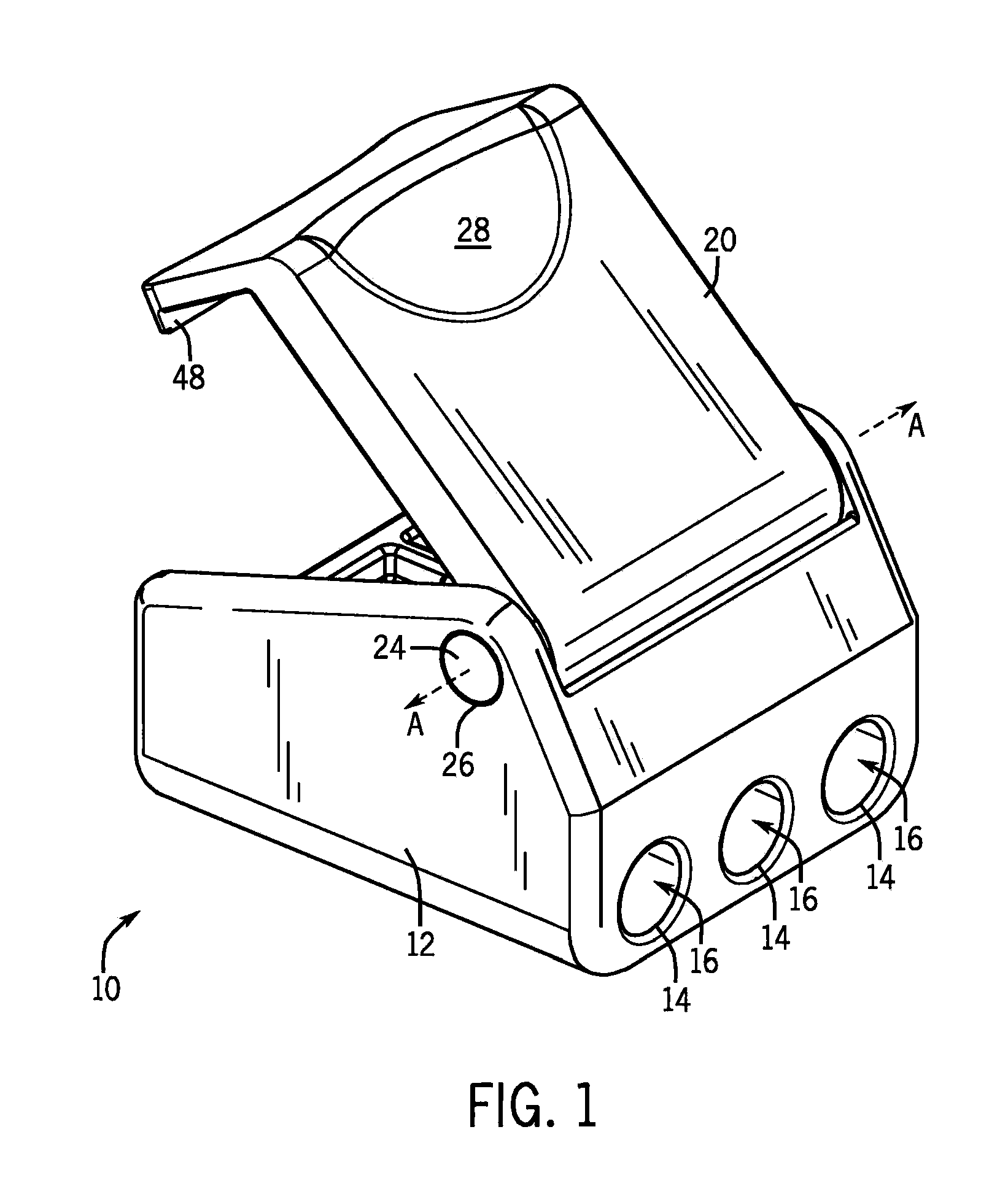
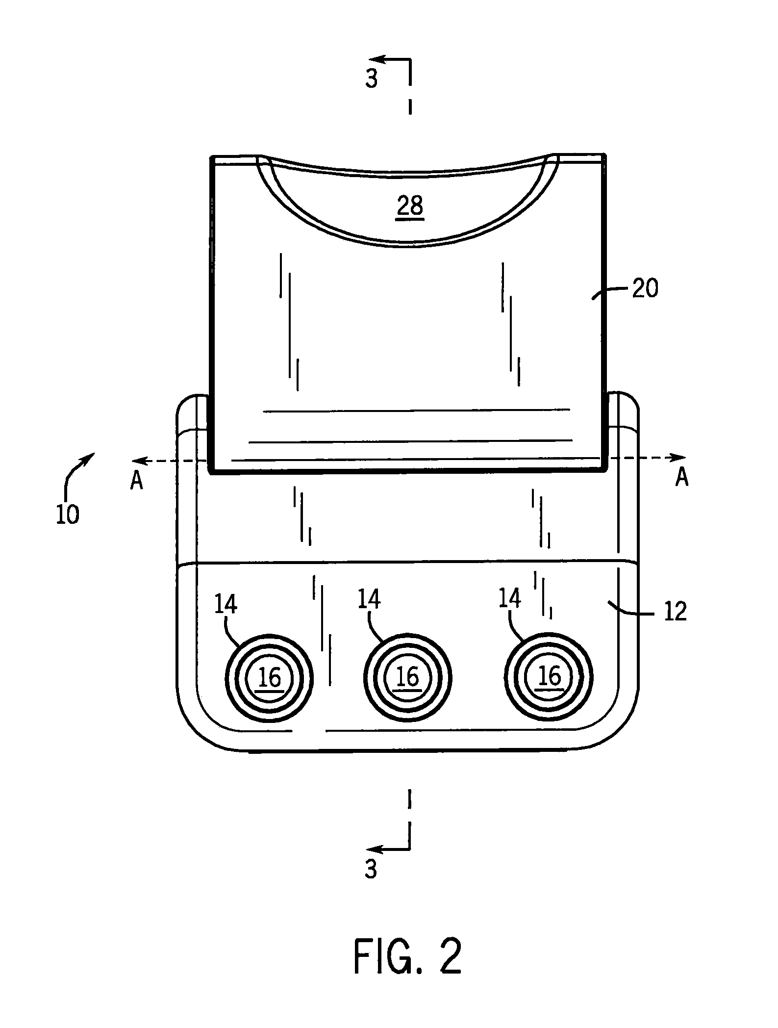
[0026]Referring first to FIGS. 1-3, an insulation displacement connector 10 is shown in the open position. The insulation displacement connector 10 has a housing 12 with a plurality of openings 14 for receiving a plurality of wires. While the plurality of channels 16 includes three channels, the insulation displacement connector 10 may have two, three, four, or more channels for receiving wires.

[0027]The plurality of openings 14 extend into the housing 12 as a plurality of channels 16, which taper inward as they extend away from the plurality of openings 14. Although the inward taper may be gradual over the distance of each of the plurality of channels 16, the plurality of channels 16 may include a step 18 on a portion of the taper. The step 18 provides a portion of the channel having a steeper rate of taper towards the axis of the channel than the rate of taper for the rest of the channel.

[0028]It should appreciated that although the plurality of channels 16 have been described as ...


PUM


Abstract

The present invention provides an insulation displacement connector that is suitable for the tool-less connection of wires of various gages. The combination of channels having a reduction in effective diameter and blades having various gaps restricts the insertion of the wires such that an appropriately-sized pair of blades can pierce the insulation to contact the metallic core of each wire. Because of this configuration, the wire connector does not require excessive force to bite down on the wires. Because a large force is not required, the insulation displacement connector can be finger operated and no separate tool is necessary.

Description

CROSS-REFERENCE TO RELATED APPLICATION[0001]This application claims the benefit of U.S. provisional patent application 60 / 933,643 filed on Jun. 7, 2007 and U.S. provisional patent application 61 / 128,742 filed on May 23, 2008. The contents of these patent applications are hereby incorporated by reference in their entirety.STATEMENT REGARDING FEDERALLY SPONSORED RESEARCH OR DEVELOPMENT[0002]Not applicable.FIELD OF THE INVENTION[0003]This invention relates to wire connectors. In particular, this invention relates to a wire connector in which blades pierce the insulation of wires to establish an electrical connection.BACKGROUND OF THE INVENTION[0004]Typically, wires have a metallic core surrounded by an insulating coating. When a current is run through the metallic core of the wire, the insulating coating assures that the current is contained within the insulation and does not deviate outside of the wire due to a short. When performing electrical work, it may be necessary to join wires ...

Claims


Application Information

Patent Timeline
Patent Type & Authority Patents(United States)
IPC IPC(8): H01R4/24
CPCH01R4/2433H01R31/085
Inventor RADLE, PATRICK J.
Owner POWER PROD
Learn More