
Method and apparatus for testing shafts

a shaft and shaft technology, applied in the field of golf club shaft testing, can solve the problems of false positive, time-consuming air cannon test, noisy, and human supervision, and achieve the effect of reducing the risk of false positiv

Active Publication Date: 2010-09-07
FUJIKURA COMPOSITE AMERICA
View PDF26 Cites 10 Cited by
  • Summary
  • Abstract
  • Description
  • Claims
  • Application Information

AI Technical Summary

Benefits of technology

"The invention provides methods and apparatus for testing shafts, such as golf club shafts. The shaft tester includes a frame, three shaft supports, an actuator, a sensor, a controller, and a motor. The actuator can displace the shaft to cause a deflection, and the sensor can output a signal corresponding to the load force exerted by the shaft. The controller can control the displacement and rotation of the shaft. The methods involve supporting the shaft at three fixed positions, displacing the shaft to cause a deflection, and measuring the load force exerted by the shaft during rotation. The results can be used to generate a fatigue life profile for the shaft. The technical effects of the invention include improved accuracy and efficiency in testing shafts for fatigue resistance."

Problems solved by technology

Additionally, air cannon tests are time consuming, noisy, require human supervision and are potentially dangerous (essentially since a projectile is launched at high speed toward the club head).
At least one problem with these methods and other composite golf shaft testing methods is that all of these tests focus on one singular location or point on the shaft and not at different points of the or the entire circumference.
This type of testing can lead to a “false positive” destructive test result.
Variations in shaft wall thickness caused by ply drop-offs or poor designs can lead to strength variations in the shaft about its circumference.

Method used


Image

  • Method and apparatus for testing shafts
  • Method and apparatus for testing shafts
  • Method and apparatus for testing shafts

Examples


Embodiment Construction

[0033]The following description is not to be taken in a limiting sense, but is made merely for the purpose of describing the general principles of exemplary embodiments. The scope of the invention should be determined with reference to the claims.

[0034]Reference throughout this specification to “one embodiment,”“an embodiment,” or similar language means that a particular feature, structure, or characteristic described in connection with the embodiment is included in at least one embodiment of the present invention. Thus, appearances of the phrases “in one embodiment,”“in an embodiment,” and similar language throughout this specification may, but do not necessarily, all refer to the same embodiment.

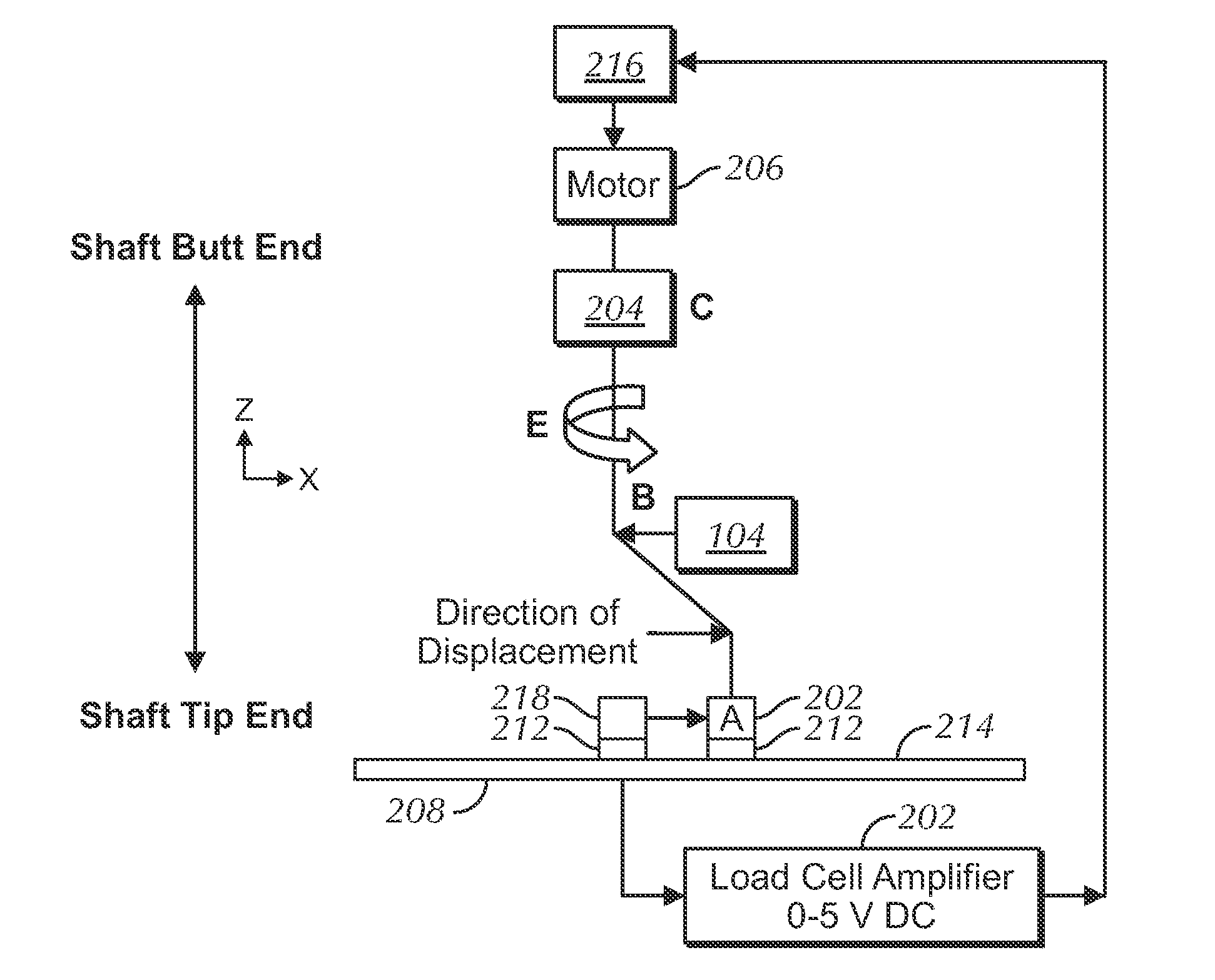
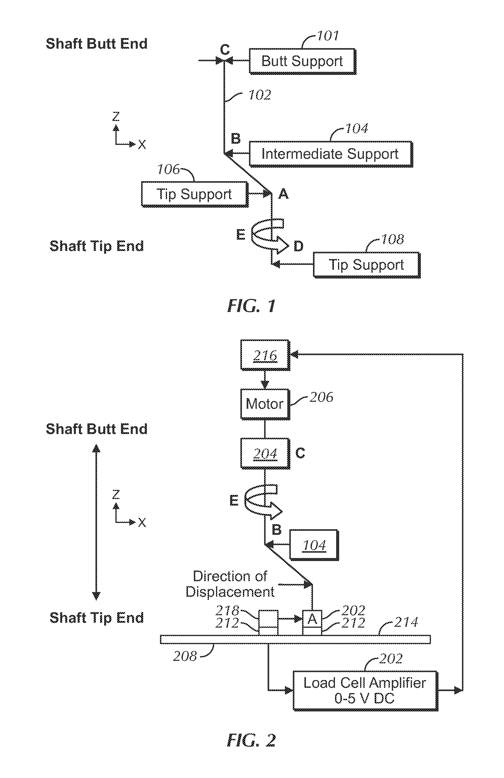
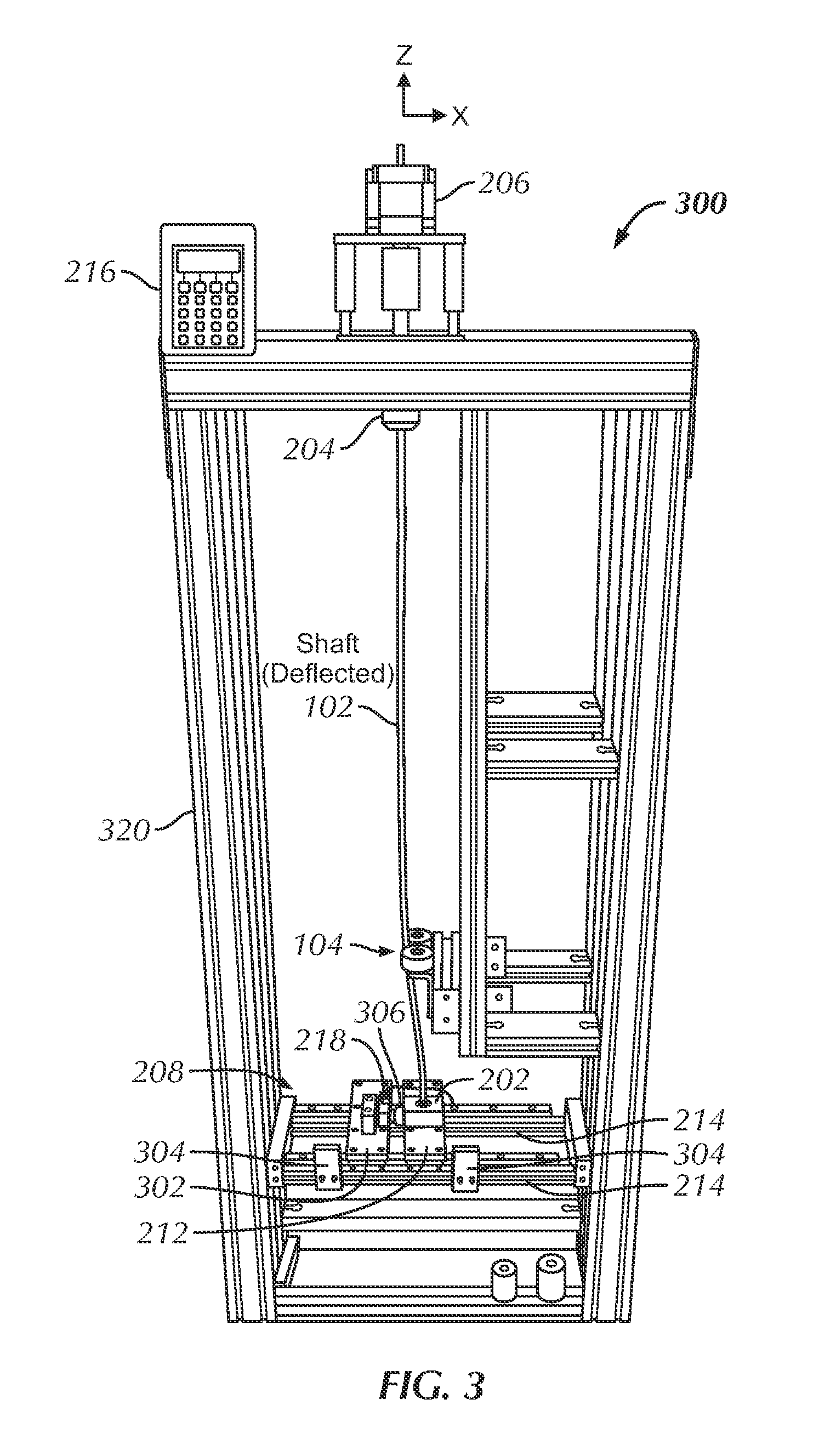
[0035]Several embodiments of the present invention addresses the problems described above. In several embodiments, a shaft testing device or machine and related methods are provided to test the characteristics of a shaft or similar elongate structure that is intended to deflect or to bend ...


PUM

PropertyMeasurementUnit
forceaaaaaaaaaa
displacementaaaaaaaaaa
speedaaaaaaaaaa

Abstract

Methods and apparatus are provided for testing shafts, such as golf club shafts. In one embodiment, the invention can be characterized as a shaft tester comprising: a frame; a first shaft support supporting a first portion of a shaft at a first fixed position; a second shaft support supporting a second portion of the shaft at a second fixed position; and a third shaft support supporting a third portion of the shaft at a third fixed position. An actuator couples to the third shaft support to displace the third portion relative to the first and second portions to deflect the shaft. A sensor couples to one of the first, second and third supports outputting a signal corresponding to a force exerted by the shaft due. A controller controls displacement of the shaft. In some embodiments, the shaft is rotated while being deflected.

Description

[0001]This application claims the benefit of U.S. Provisional Application No. 60 / 914,015, filed Apr. 25, 2007, which is incorporated in its entirety herein by reference.BACKGROUND OF THE INVENTION[0002]1. Field of the Invention[0003]The present invention relates generally to the testing shafts, and more specifically to testing of golf club shafts.[0004]2. Discussion of the Related Art[0005]Currently there are a variety of devices to test the durability of a shaft. Different tests have been designed and developed to filter out shafts that don't have acceptable structural strength. For example, in the golf industry, a commonly used shaft destruction test is the air cannon test, whereby a ball is shot at a golf head at a specified speed until an acceptable impact quantity is reached or there is a catastrophic break (the head is bonded to the shaft as would be in the field). This test requires multiple iterations (often times up to 3000 hits and beyond). Additionally, air cannon tests a...

Claims


Application Information

Patent Timeline
Patent Type & Authority Patents(United States)
IPC IPC(8): G01N3/20
CPCG01N3/04G01N2033/008G01N2203/0021G01N33/008
Inventor DEE, ALEX T.XI, ZHICHENCHAMBERLAIN, MARK
Owner FUJIKURA COMPOSITE AMERICA
Learn More