
Cellular radio communication systems and methods and equipment for use therein

a technology of cellular radio communication and equipment, applied in substation equipment, power management, electrical equipment, etc., can solve the problems of decreasing the output operational power level of neighbouring co-channel base stations, and achieve the effects of increasing wide area coverage, and decreasing the output operational power level

Active Publication Date: 2010-08-24
MOTOROLA SOLUTIONS INC
View PDF9 Cites 21 Cited by
  • Summary
  • Abstract
  • Description
  • Claims
  • Application Information

AI Technical Summary

Benefits of technology

[0019]More particularly, in the event that a single base station becomes isolated from the system, a first form of the method is as follows. This form may be applied as a fallback procedure in the situation where the isolated base station is designated by the system to be favoured, e.g. a concentrated group of mobile units exists or is expected to exist near to that base station and / or that base station provides a relatively wide area coverage compared with neighbouring co-channel stations which are base stations operating on the same frequency as the isolated station. The favoured designation may have been previously set during system design and implementation or it may be detected by the system on the occasion when the isolation event occurs. This form of the method includes increasing the output operational power level of the isolated base station, whilst possibly also decreasing the output operational power level of neighbouring co-channel base stations. This form of the method increases C / I ratio over the coverage area of the isolated base station, thus extending the coverage area of the isolated base station and this facilitates more mobile units remaining linked to this base station or switching over to this base station from co-channel base stations of neighbouring cells.
[0020]A second form of the method may be applied as a fallback procedure in the situation where the isolated base station is not designated by the system to be favoured, i.e. the number of mobile units linked to the station is or is expected to be lower than the number linked to neighbouring co-channel stations and / or the area of coverage provided by the station is smaller than that provided by neighbouring co-channel stations. The unfavoured designation may have been previously set during system design and implementation or it may be detected by the system on the occasion when the isolation event occurs. The second form of the method includes decreasing (including where appropriate reducing to zero) the output operational power level of the isolated base station, whilst possibly also increasing the output power level of neighbouring co-channel base stations. This decreases the C / I ratio of the isolated station and shrinks the coverage area of the isolated station facilitating mobile units to switch over, or stay linked, to neighbouring base stations.
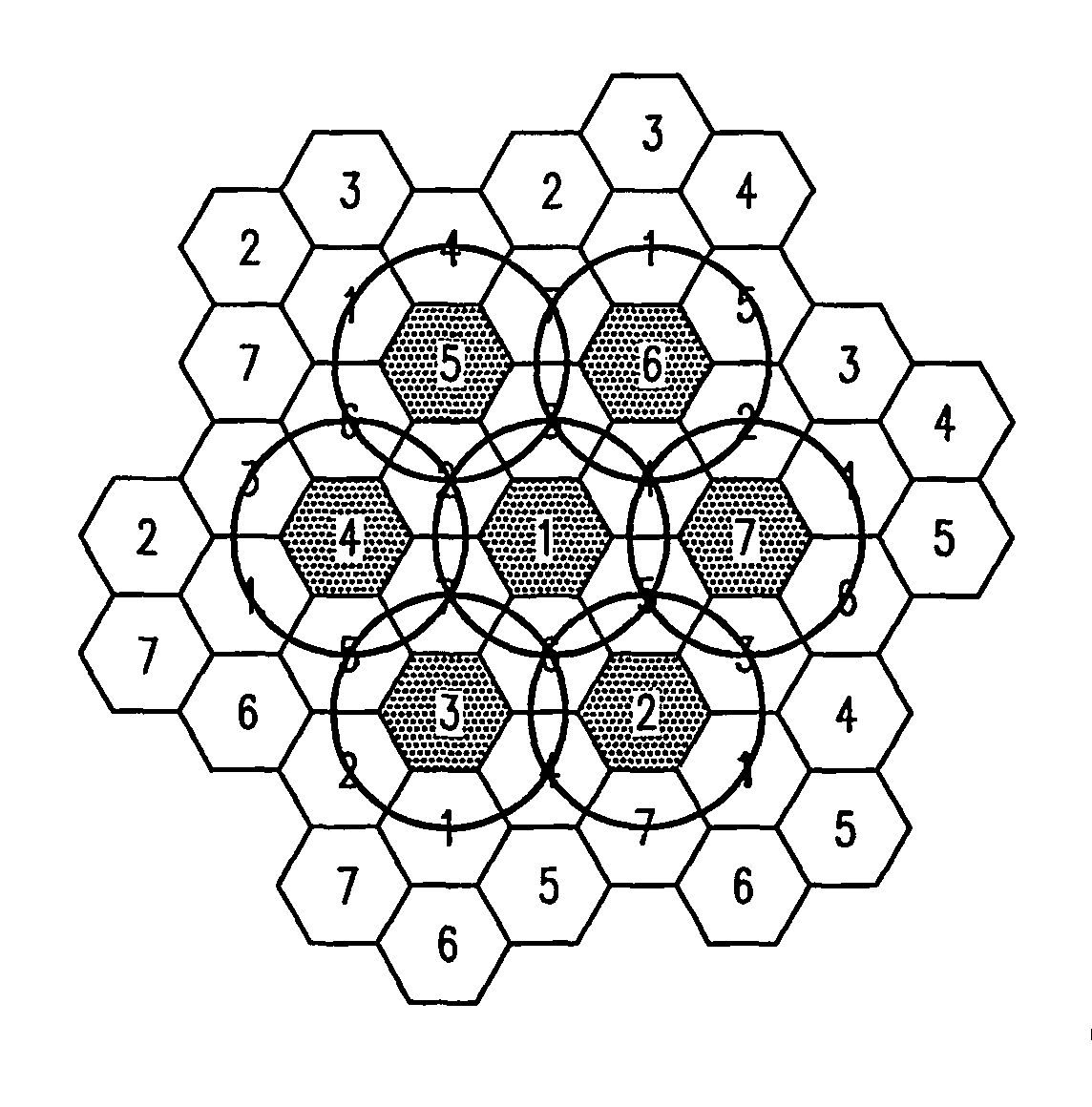
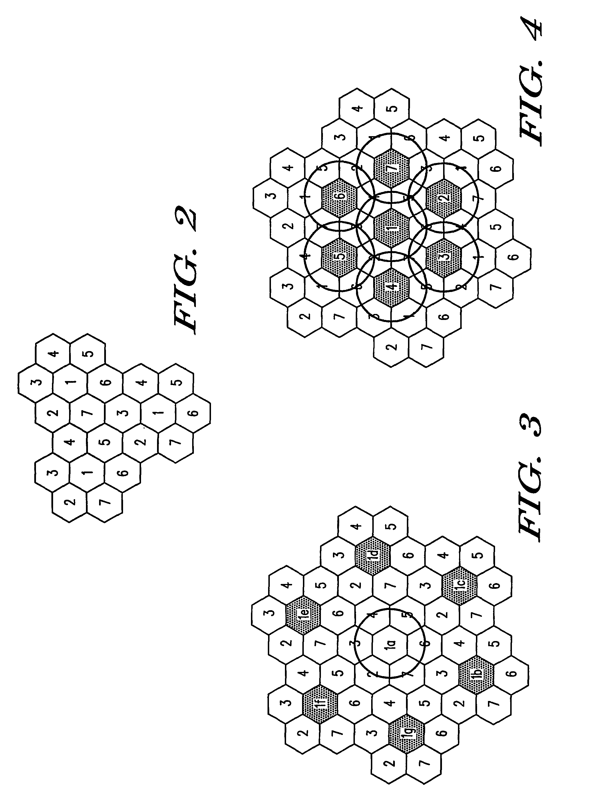
[0021]A third form of the method of the invention may be applied as a fallback procedure in the situation where many or all of the base stations become isolated, e.g. owing to a system failure. This form includes having certain base stations designated as key stations, according to their expected higher degree of common coverage of mobile units, and having other base stations, having a lower expected degree of coverage, designated as non-key stations. This form of the method further includes, in the event of isolation of a large number of the base stations, e.g. due to a network failure, increasing or at least maintaining the output operational power level of all key stations, whilst possibly also decreasing or switching off the power level of other base stations, designated as non-key stations. The range of the key stations is thereby extended and this facilitates more mobile units being allowed to link, or remain linked, to key base stations.

Problems solved by technology

Thus, a fallback mode of operation is initiated such that some mobile units served by the isolated base station may remain in mutual communication with the isolated based station.
This form of the method includes increasing the output operational power level of the isolated base station, whilst possibly also decreasing the output operational power level of neighbouring co-channel base stations.

Method used


Image

  • Cellular radio communication systems and methods and equipment for use therein
  • Cellular radio communication systems and methods and equipment for use therein
  • Cellular radio communication systems and methods and equipment for use therein

Examples


Embodiment Construction

[0036]The manner in which the invention satisfies the stated needs described earlier will now be explained with respect to each of the problem situations described in the Background section of this specification. The following description is exemplary in terms of a Private Mobile Radio (PMR) system, with base stations having direct connection capability. The invention may however be applicable also to other types of cellular systems, with modifications which will be readily apparent to persons skilled in the art. The method of the invention calls for measures to be taken on two different occasions—(1) upon setting up and programming (or re-programming) a particular cellular system and (2) when a fault is detected. The first mentioned occasion may even extend back to the planning phase of the system, whereby some of its characteristics (notably cell boundaries and channel allocation) may be determined iteratively with the needs of fallback procedures, especially when operating accord...


PUM


Abstract

Disclosed is a method of operation for use in a radio communications system comprising a cellular network of base stations and mobile units linked to the base stations. The method comprises detecting that a base station has become isolated from the system, wherein the isolated base station has lost at least one link to other base stations but is still in radio communication with its mobile units and changing an output power level of said isolated base station relative to an output power level of one or more selected co-channel base stations of neighboring cells of the cellular system, whereby the range of communications provided by said isolated base station is changed to a different finite value relative to that provided by the said co-channel base stations.

Description

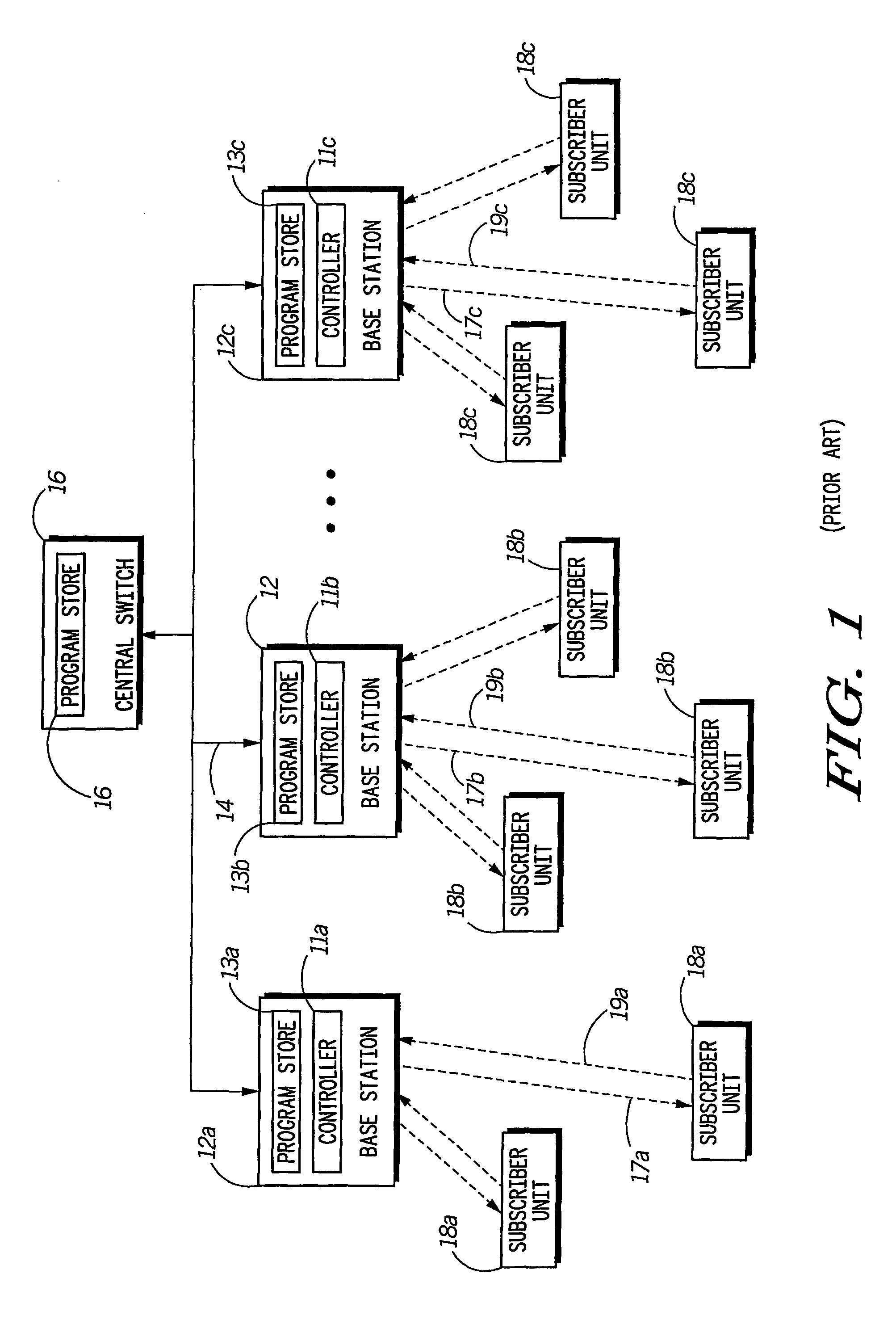
[0001]This application claims the benefit of prior filed co-pending international application Serial No. PCT / EP02 / 03093 filed Mar. 18, 2002, and assigned to Motorola, Inc., which was published by the International Bureau on Nov. 14, 2002 under No. WO 02 / 091622A1; and Great Britain application Serial No. 0111317.4 filed May 9, 2001.FIELD OF THE INVENTION[0002]This invention relates to cellular radio communication systems and methods and equipment for use therein. More particularly, the invention relates to systems comprising a cellular network of base stations each serving mobile units in its location and a method for maintaining interconnection between mobile units in the event of accidental isolation of one or more of the base stations from the system.BACKGROUND OF THE INVENTION[0003]A cellular radio communication system, such as illustrated in the block diagram of FIG. 1 of the accompanying drawings, generally consists of an array of base transceiver stations 12 that are deployed ...

Claims


Application Information

Patent Timeline
Patent Type & Authority Patents(United States)
IPC IPC(8): H04W24/00H04B7/005H04W24/02H04W52/40
CPCH04W24/04H04W52/40
Inventor CHATER-LEA, DAVID
Owner MOTOROLA SOLUTIONS INC
Learn More