End effector mechanism for a surgical instrument
a surgical instrument and end effector technology, applied in the field of surgical instrument end effector mechanism improvement, can solve the problems of difficult grasp, high slippery and difficult to grasp, and the inability to meet the holding power of these instruments, and achieve the effect of improving the end effector mechanism
- Summary
- Abstract
- Description
- Claims
- Application Information
AI Technical Summary
Benefits of technology
Problems solved by technology
Method used
Image
Examples
first embodiment
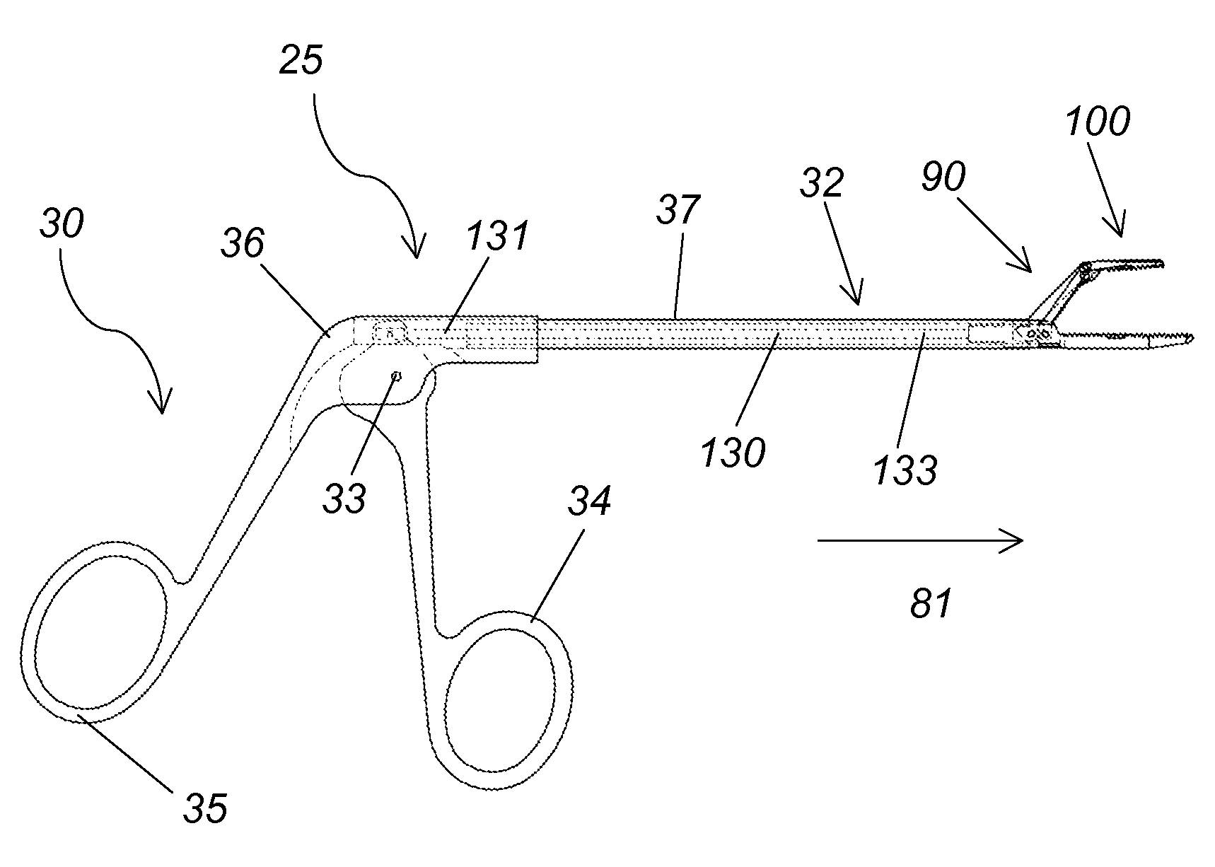
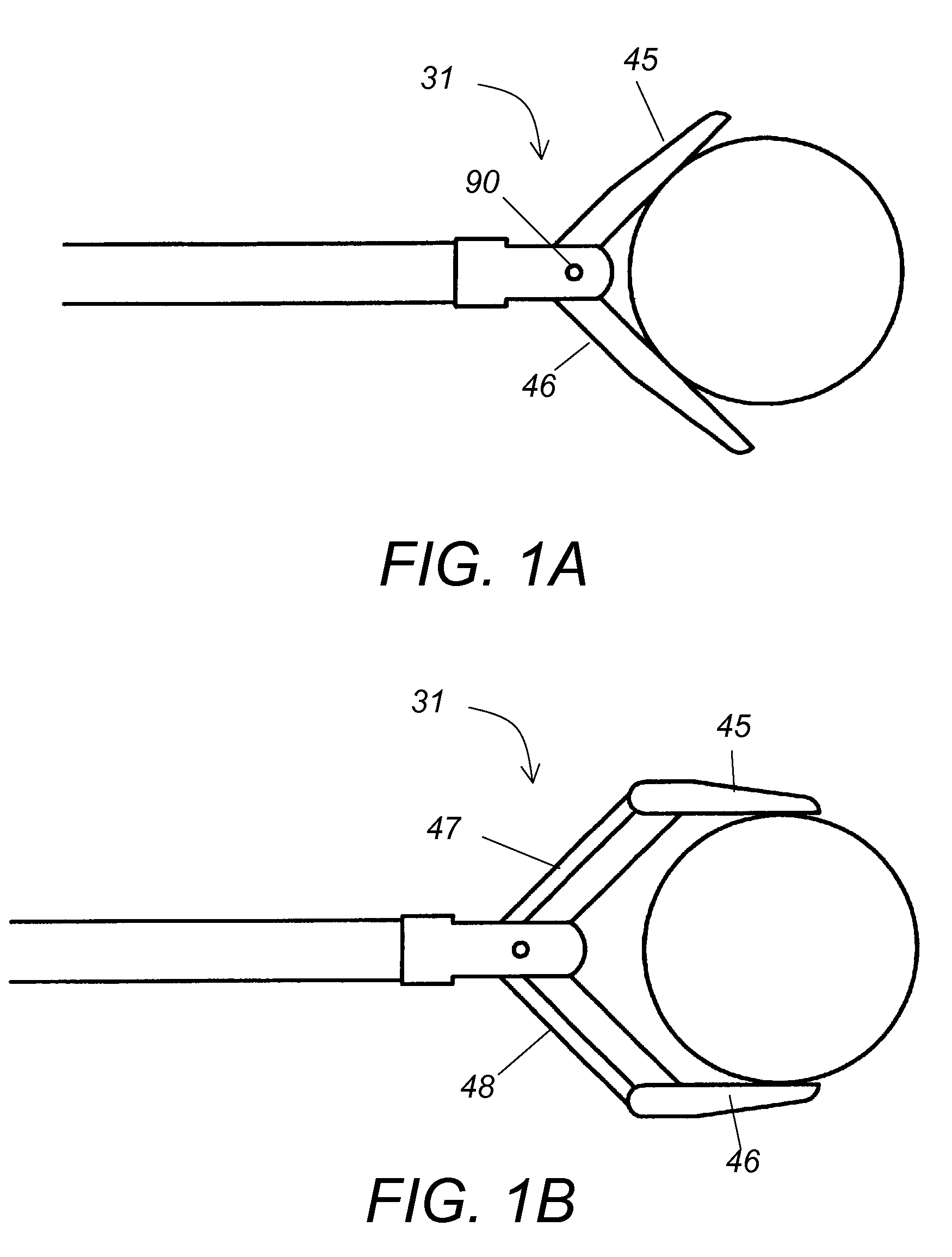
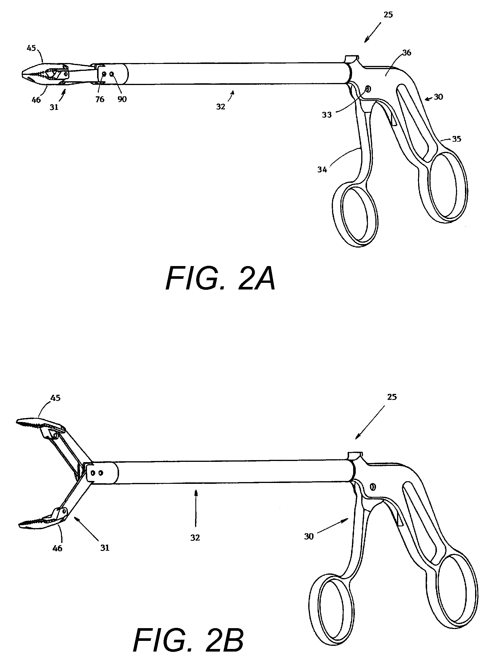
[0067]Referring to FIG. 3 and FIG. 7, an end effector assembly 90 includes a housing 140 and the end effector mechanism 100. Housing 140 includes a hollow tube having one end 140a connected to a distal end of the outer hollow sheath 37 and a second end 140b connected to the end effector mechanism 100. Housing end 140b also includes through openings 142, 144. Actuator 132 is disposed within housing 140. End effector mechanism 100 includes a stationary jaw 110 extending longitudinally from the second end 140b of housing 140 and a movable jaw 120 pivotally connected to the second end 140b of housing 140. Movable jaw 120 includes a first jaw element 122, second jaw element 124 and drive element 126. Drive element 126 has one end 126a pivotally connected to the second end 140b of housing 140 by inserting pivot pin 125 into through-opening 144 of the housing 140 and through-opening 146 of the drive element 126. A second end 126b of the drive element 126 is pivotally connected to a first e...
third embodiment
[0070]Referring to FIG. 12 and FIG. 14 the end effector mechanism 100, includes first and second sets of movable jaws 110, 120. First set of movable jaws 110 includes first and second jaw elements 112, 114 and drive element 116. Second set of movable jaws 120 includes first and second jaw elements 122, 124 and drive element 126. Both drive elements 116, 126 are actuated with one actuation rod 130 that reciprocates coaxially within the hollow sheath 37 in response to manipulation of the movable handle 34 by the user. Moving the handle 34 away from the stationary handle 35 pushes the actuator rod 132 backward in the direction of 80, shown in FIG. 10C and this backward motion of the actuator rod 132 causes the drive elements 116, 126 to rotate downward and upward, respectively, thereby opening the first and second movable jaw sets 110, 120. The location of pivot pin 125 connecting drive elements 116, 126 to the housing 140 is varied by an additional pivot driver mechanism 160, as was d...
fourth embodiment
[0071]Referring to FIG. 15 and FIG. 17 the end effector mechanism 100, includes first and second sets of movable jaws 110, 120. First set of movable jaws 110 includes first and second jaw elements 112, 114 and drive element 116. Second set of movable jaws 120 includes first and second jaw elements 122, 124 and drive element 126. Drive elements 116, 126 are actuated with two separate actuation rods 130a, 130b that reciprocate coaxially within the hollow sheath 37 in response to manipulation of two separate movable handles 34a, 34b by the user, shown in FIG. 18A and FIG. 19. Moving the handles 34a, 34b away from the stationary handle 35 pushes the actuator rods 130a, 130b backward in the direction of 80, shown in FIG. 18A and this backward motion of the actuator rods 130a, 130b causes the drive elements 116, 126 to rotate downward and upward, respectively, thereby opening the first and second movable jaw sets 110, 120. Since there are two separate handles 34a, 34b that can be moved se...
PUM
 Abstract
Description
Claims
Application Information
 - R&D
- Intellectual Property
- Life Sciences
- Materials
- Tech Scout
- Unparalleled Data Quality
- Higher Quality Content
- 60% Fewer Hallucinations
Browse by: Latest US Patents, China's latest patents, Technical Efficacy Thesaurus, Application Domain, Technology Topic, Popular Technical Reports.
© 2025 PatSnap. All rights reserved.Legal|Privacy policy|Modern Slavery Act Transparency Statement|Sitemap|About US| Contact US: help@patsnap.com


