
Nozzle devices

a technology of nozzles and nozzles, which is applied in the direction of liquid transfer devices, single-unit devices, and guards, etc., can solve the problems of requiring operators, devices that are difficult to actuate using other parts of the body than fingers, and devices that are generally less suitable for certain individuals, so as to reduce the extent, reduce the effect of pressing space and reducing the exten

Inactive Publication Date: 2010-08-17
INCRO LTD
View PDF16 Cites 21 Cited by
  • Summary
  • Abstract
  • Description
  • Claims
  • Application Information

AI Technical Summary

Benefits of technology

[0017]The nozzle device of the present invention solves the aforementioned problems associated with many conventional pump-action spray nozzle devices by providing a device which is extremely simple in design and which will typically comprise no more than six separate component parts that are fitted together to form the assembled nozzle device. In preferred embodiments the device will comprise no more than three component parts or, more preferably, two separate component parts or, even more preferably, the device is formed from a single, integrally formed component part. By “separate component parts” we mean that the parts are not linked together in any way, i.e. they are not integrally formed with one another (but each separate component part may comprise one or more integral parts or portions). The key to reducing the number of components lies in the formation of the necessary features integrally within the body of the device. For instance, the chamber, inlet, inlet valve, outlet, and outlet valve can all be defined by the body, thereby reducing the need to include separate components with all the consequential increases in component and assembly costs.
[0109](ii) subsequently return to its initial position when the applied pressure is removed, thereby causing the volume of the chamber to increase and the pressure therein to fall such that fluid is drawn into the chamber through the inlet valve;

Problems solved by technology

A problem with the aforementioned devices is that an operator is required to press the resiliently deformable dome-shaped portion inwards using their thumb or finger in order to dispense fluid from the internal chamber.
This requires a certain amount of co-ordination on the part of the operator as well as a reasonable amount of pressure, which makes such devices generally less suitable for certain individuals.
Furthermore, such devices are difficult to actuate using portions of the body other than a finger, such as the palm of the hand, wrist or elbow.

Method used


Image

  • Nozzle devices
  • Nozzle devices
  • Nozzle devices

Examples


Embodiment Construction

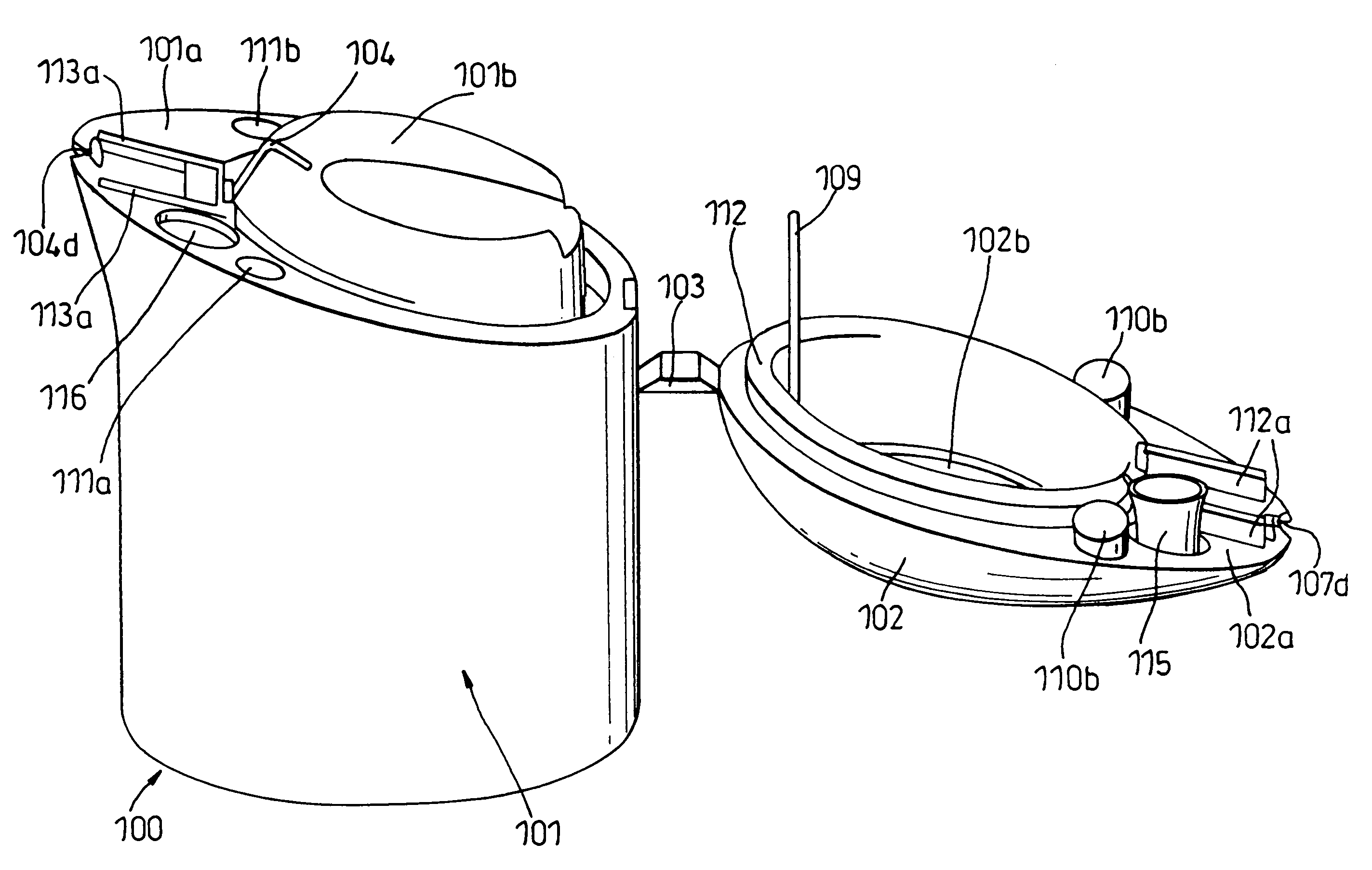
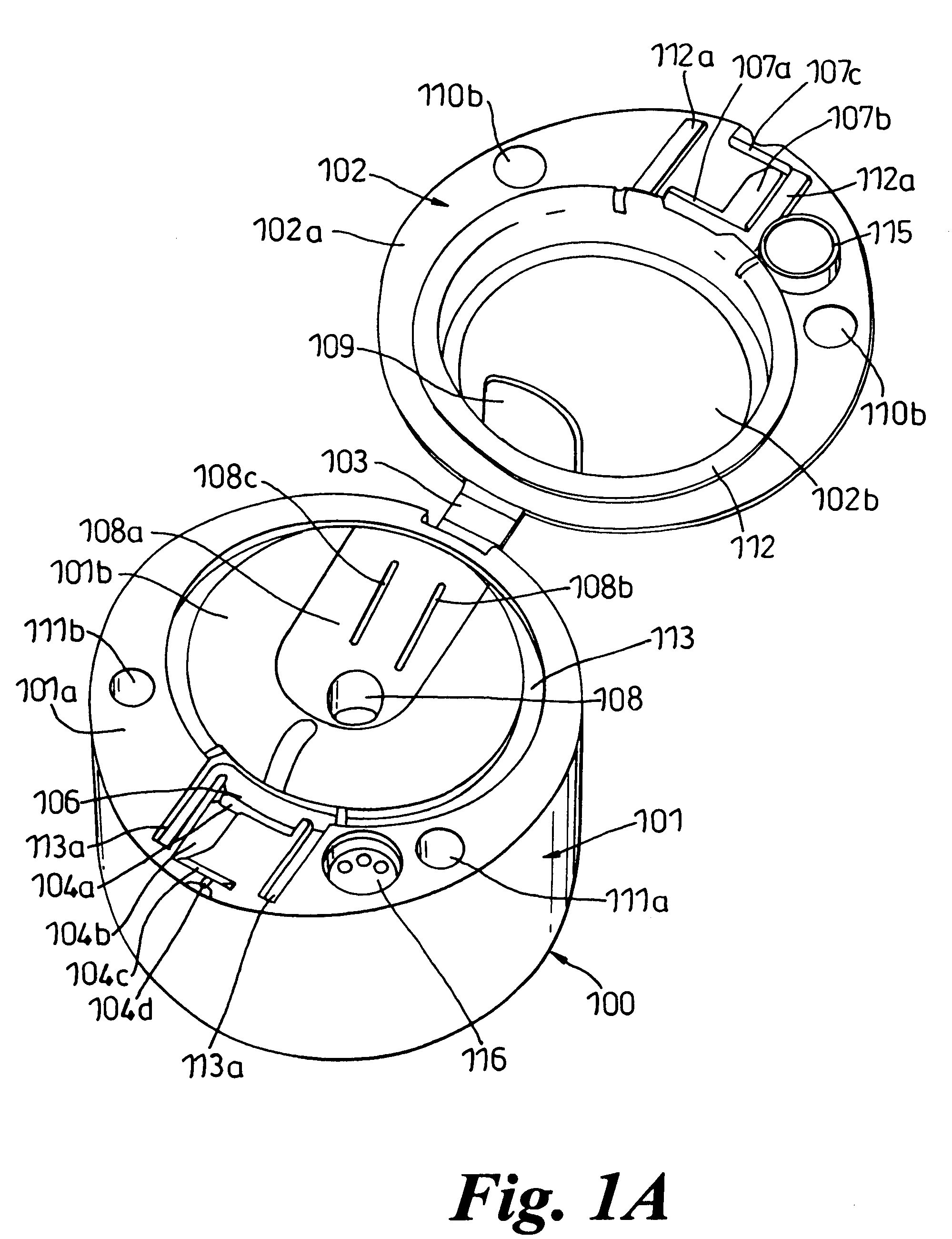
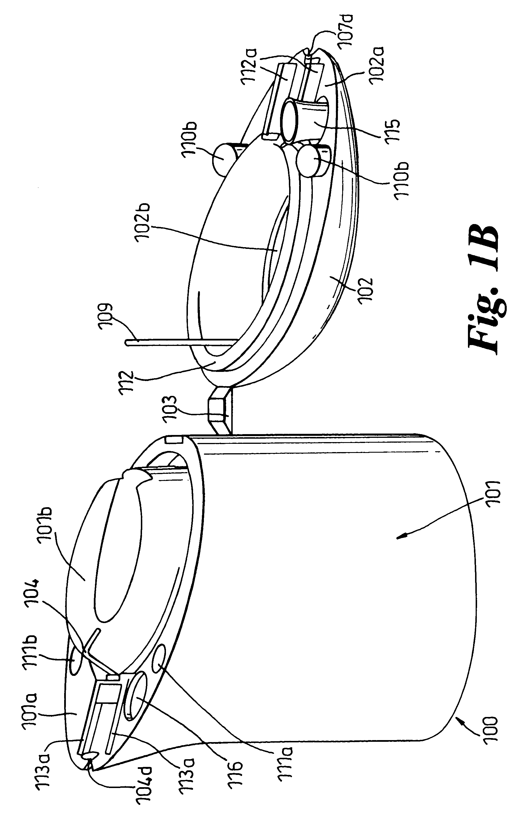
[0160]The nozzle device shown in FIGS. 1A and 1B comprises a body 100 formed of two parts, namely a base part 101 and an upper part 102, which are connected to one another by a foldable connection element 103.

[0161]The body 100 is formed from a single rigid plastic material in a single moulding operation. The device will be moulded in the configuration shown in FIGS. 1A and 1B and then the upper part 102 will be folded over about the connection element 103 and fitted to the upper surface of the base 101 to form the assembled nozzle arrangement. Once the base 101 and the upper part 102 are fitted together, the portion 102a of the under surface of the upper part 102 abuts the abutment portion / surface 101a of the upper surface of the base 101. The elevated portion 101b of the upper surface of the base 101 is received within recess 102b formed in the under surface of the upper part 102 to define an internal chamber.

[0162]A groove 104 formed in the elevated portion of the base 101b forms...


PUM


Abstract

This invention relates to pump-action nozzle devices methods of making the same. The nozzle devices of the invention comprises a body which defines an internal chamber having an inlet through which fluid may be drawn into said chamber and an outlet through which fluid present in the chamber may be expelled from the nozzle. The inlet comprises an inlet valve and the outlet comprises an outlet valve. Fluid is dispensed from the dispenser nozzles by applying pressure to an actuator member that engages and resiliently deforms or displaces a portion of the body of the device that defines the chamber, thereby compressing the chamber and actuating the dispensing of fluid. In preferred embodiments, the actuator provides a rigid actuator surface that an operator can apply a pressure to.

Description

CROSS REFERENCE TO RELATED APPLICATIONS[0001]This application is a continuation of application Ser. No. 10 / 545,592, filed on Apr. 21, 2006, now U.S. Pat. No. 7,357, 335 which is the National Stage of International Application No. PCT / GB2004 / 000614, filed Feb. 17, 2004, and which is incorporated herein by reference and claims priority of Applications No. GB0400857.7, filed Jan. 15, 2004; GB0327423.0, filed Nov. 25, 2003; GB0320720.6, filed Sep. 4, 2003; GB0318022.1, filed Aug. 1, 2003; GB0310244.9, filed Mar. 5, 2003; GB0308909.1, filed Apr. 17, 2003; GB0305597.7, filed Mar. 12, 2003, and G03003698.5, filed Feb. 18, 2003.BACKGROUND OF THE INVENTION[0002]1. Field of the Invention[0003]This invention relates to nozzle devices and, more particularly but not exclusively, to pump-action nozzle devices and methods of making such devices.[0004]2. Description of Related Art[0005]Pump-action nozzle devices are commonly used to provide a means by which fluids can be dispensed from a non-pressu...

Claims


Application Information

Patent Timeline
Patent Type & Authority Patents(United States)
IPC IPC(8): B62C11/00B05B1/34B05B11/00B67D7/70B05B11/04B05B11/06B65D83/14B65D83/16B67D7/58
CPCB05B11/0027B05B11/007B05B11/0072B05B11/06B05B11/3011B05B11/3028B05B11/303B05B11/3032B05B11/3033B05B11/3059B05B11/3084B05B11/3085B05B11/3087B65D83/207B65D83/753B65D83/7535B65D83/22B05B11/04B65D83/56B05B11/1011B05B11/1028B05B11/103B05B11/1033B05B11/1032B05B11/1053B05B11/1059B05B11/1085B05B11/1084B05B11/1087B05B11/1097
Inventor LAIDLER, KEITHRODD, TIMOTHY
Owner INCRO LTD
Learn More