
Kitchen appliance having floating glass panel

a technology of floating glass panels and kitchen appliances, which is applied in the direction of domestic stoves or ranges, heating types, and domestic cooling devices, etc., can solve the problems of glass panel not being removed, seamless appearance, and the rim piece affecting the overall aesthetic appearance of the applian

Active Publication Date: 2010-08-10
MAYTAG
View PDF56 Cites 65 Cited by
  • Summary
  • Abstract
  • Description
  • Claims
  • Application Information

AI Technical Summary

Benefits of technology

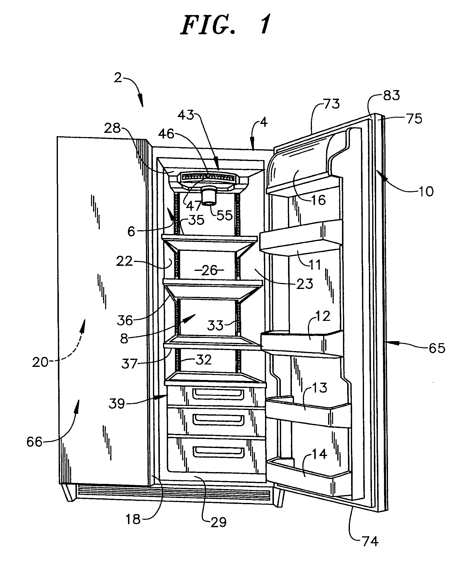
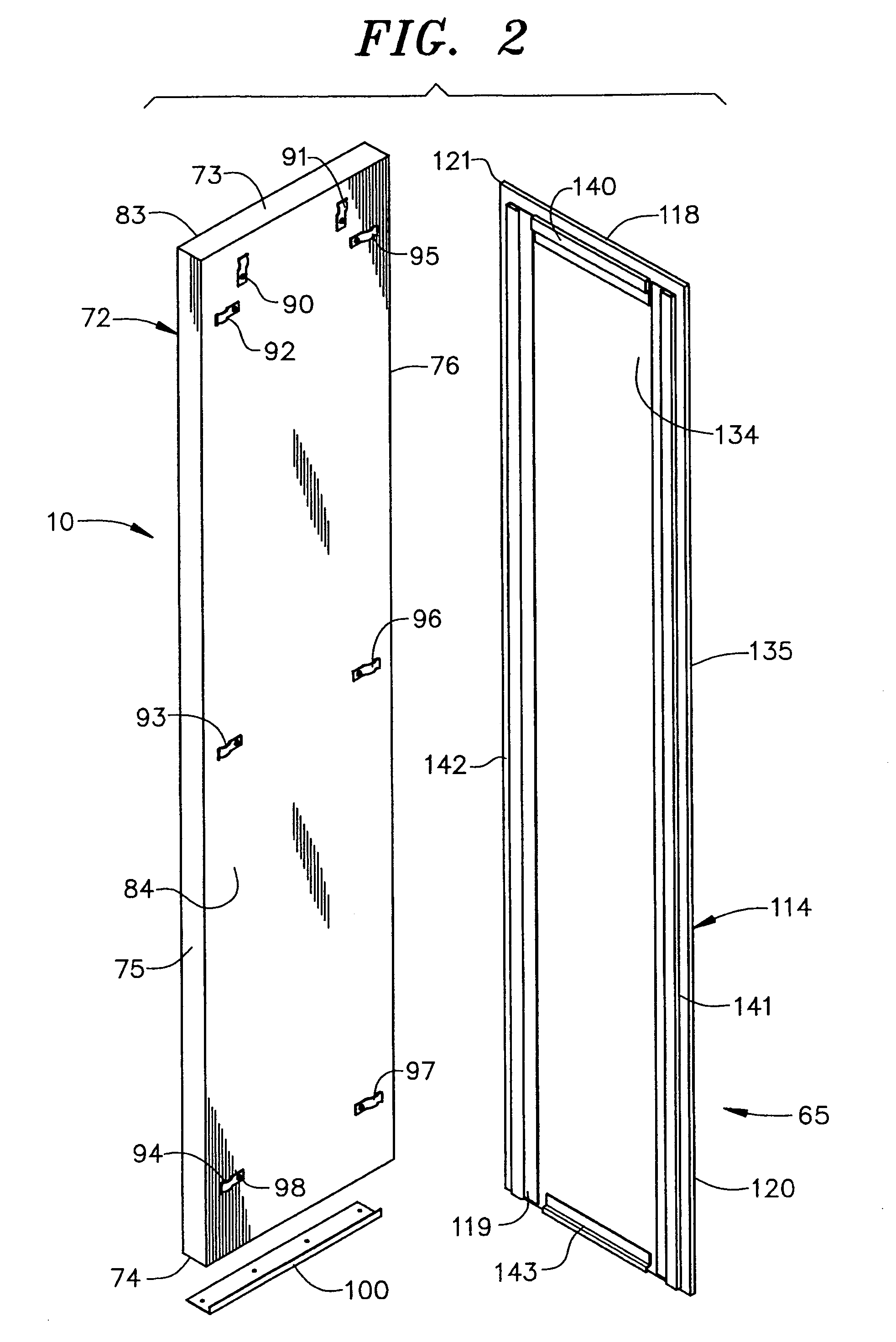
"The present invention is about mounting a glass panel on a kitchen appliance's door. The glass panel is attached to the door using mounting members and mounting elements that are not visible when the door is closed. This creates a unique appearance where the glass panel appears to be floating relative to the door. The technical effect of this invention is to provide a more visually appealing and unique appearance for a kitchen appliance's door."

Problems solved by technology

While effective at holding the glass panel on the door, the trim piece visibly detracts from an overall aesthetic appearance of the appliance.
While this method results in a somewhat seamless appearance, once installed, the glass panel cannot be removed without causing some damage either to the glass panel itself or the door.
More importantly, mounting a glass panel in this fashion detracts from the aesthetics provided by glass.
While this method also results in a somewhat seamless appearance, once installed, the glass front panel cannot be easily removed.
If the glass panel is ever cracked or a different finish is desired, removing the panel from the appliance would prove difficult.

Method used


Image

  • Kitchen appliance having floating glass panel
  • Kitchen appliance having floating glass panel
  • Kitchen appliance having floating glass panel

Examples


second embodiment

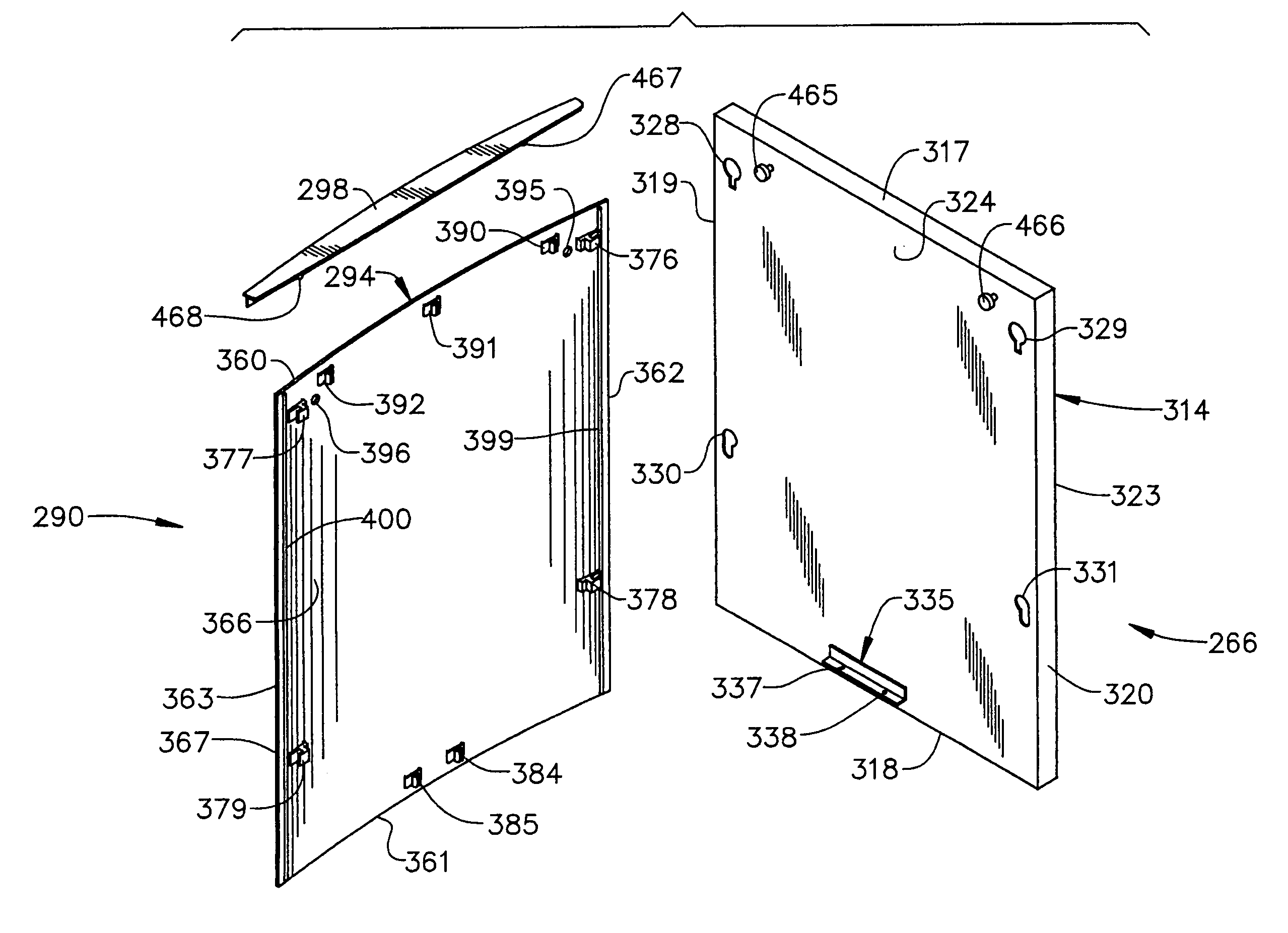
[0033]Reference will now be made to FIGS. 5-7 in describing a kitchen appliance 250 constructed in accordance with the present invention. As shown, kitchen appliance 250 takes the form of a dishwasher having a support body or frame member 253 that supports a dishwashing compartment 255. As shown, dishwasher 250 is arranged below a kitchen countertop 258 adjacent cabinetry 261. At this point, it should be understood that, while dishwasher 250 is shown as a conventional-type dishwasher, the present invention can be incorporated into other model types, such as dishwashers having various slide-out washing compartments.

[0034]Dishwasher 250 includes a door 266 that pivots about a generally horizontal axis to selectively reveal a frontal opening (not separately labeled) to enable the loading and unloading of dishes into dishwashing compartment 255. Towards that end, door 266 is provided with a handle 274 having a crosspiece 278 as well as first and second support members 280 and 281. In th...

third embodiment

[0040]Reference will now be made to FIG. 10 in describing a kitchen appliance 476 constructed in accordance with the present invention. In the embodiment shown, kitchen appliance 476 constitutes an oven range having a support body or cabinet 479. While shown as a freestanding oven range, kitchen appliance 476 could take various forms, such as a slide-in range or wall oven. In any case, kitchen appliance 476 includes an upper cooking surface or cooktop 483 provided with a plurality of cooking zones 486-490 below which is arranged an oven 493. In a manner known in the art, oven 493 is provided with an oven cavity 496 having a frontal opening (not labeled) which is selectively accessed through a door 500.

[0041]In a manner also known in the art, door 500 is shown to include a smooth glass surface 510 having a central transparent zone 511 that allows a consumer to view the contents of oven cavity 496 when door 500 is closed. Door 500 is also provided with a handle 515, as well as a plura...


PUM

PropertyMeasurementUnit
temperatureaaaaaaaaaa
strengthaaaaaaaaaa
distanceaaaaaaaaaa

Abstract

A kitchen appliance includes a door having an outer panel portion and an inner panel portion, with a plurality of mounting members being spaced about the outer panel portion of the door. A glass panel assembly, including a glass panel and a plurality of mounting elements, is detachably mounted to the door through the interengagement of the plurality of mounting elements with the plurality of mounting members. The mounting elements are adhesively secured to the glass panel. Neither the plurality of mounting members nor the plurality of mounting elements are readily visible normally when viewing the kitchen appliance such that the glass panel appears to float relative to the door.

Description

BACKGROUND OF THE INVENTION[0001]1. Field of the Invention[0002]The present invention pertains to the art of kitchen appliances and, more particularly, to mounting a decorative glass panel to an appliance door such that the glass panel appears to float relative to the appliance door.[0003]2. Discussion of the Prior Art[0004]Providing a decorative facade to kitchen appliances is well known in the art. The decorative facade allows the appliance to “tie-in” to overall kitchen décor. The decorative facade can take on a variety of forms from something as simple as a coat of paint to made to order wooden panels that match adjacent cabinetry. In many cases the decorative panel takes the form of a replaceable plastic or metal sheet that is mounted to a door of the appliance with peripheral trim components.[0005]In addition to mounting wood, plastic or metal panels to appliance doors, it is now quite common to employ glass panels. Typically, the glass panel is secured to the appliance throug...

Claims


Application Information

Patent Timeline
Patent Type & Authority Patents(United States)
IPC IPC(8): A47B17/04
CPCE06B3/7001F24C15/045F25D23/02F25D2400/18Y10T29/49826
Inventor DAVIS, NORMAN B.ERTZ, LAWRENCE J.FREESMEIER, JONHARING, STEVEN M.ROTTER, CHAD JONATHANTULLER, BARRY E.
Owner MAYTAG
Learn More