
Multiphase converter apparatus and method

a multi-phase converter and apparatus technology, applied in the direction of electric variable regulation, process and machine control, instruments, etc., can solve the problems of difficulty in installation, repair, and power conversion efficiency and effectiveness, and achieve the effect of reducing the cost of installation, repair and maintenan

Active Publication Date: 2010-08-03
THE BOARD OF TRUSTEES OF THE UNIV OF ILLINOIS
View PDF11 Cites 80 Cited by
  • Summary
  • Abstract
  • Description
  • Claims
  • Application Information

AI Technical Summary

Benefits of technology

"The present invention provides an ac / ac converter that can convert a pulsating dc input with encoded sinusoidal modulation into a multiphase modulated output. The converter includes a bridge with switch legs that modulate the pulsating dc input at a carrier frequency over multiple phases. A controller is used to activate each switch leg for modulation, ensuring that each phase has a unity power factor. The technical effect of this invention is the ability to efficiently and accurately convert pulsating dc input into a multiphase modulated output."

Problems solved by technology

However, various barriers exist to efficient and effective power conversion.
Such transformers, though, can be quite large (e.g., tens of tons), bringing difficulties for installation, repair, etc.
In spite of advances in power conversion, several problems remain.
One significant problem is switching loss of the converter.
Another problem is the significant stresses (e.g., voltage, current stresses, electromagnetic emissions) on high-frequency, high-voltage devices.

Method used


Image

  • Multiphase converter apparatus and method
  • Multiphase converter apparatus and method
  • Multiphase converter apparatus and method

Examples


case 1 (

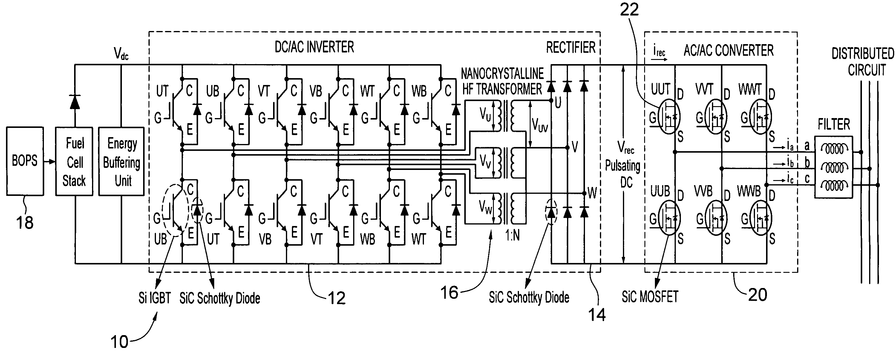
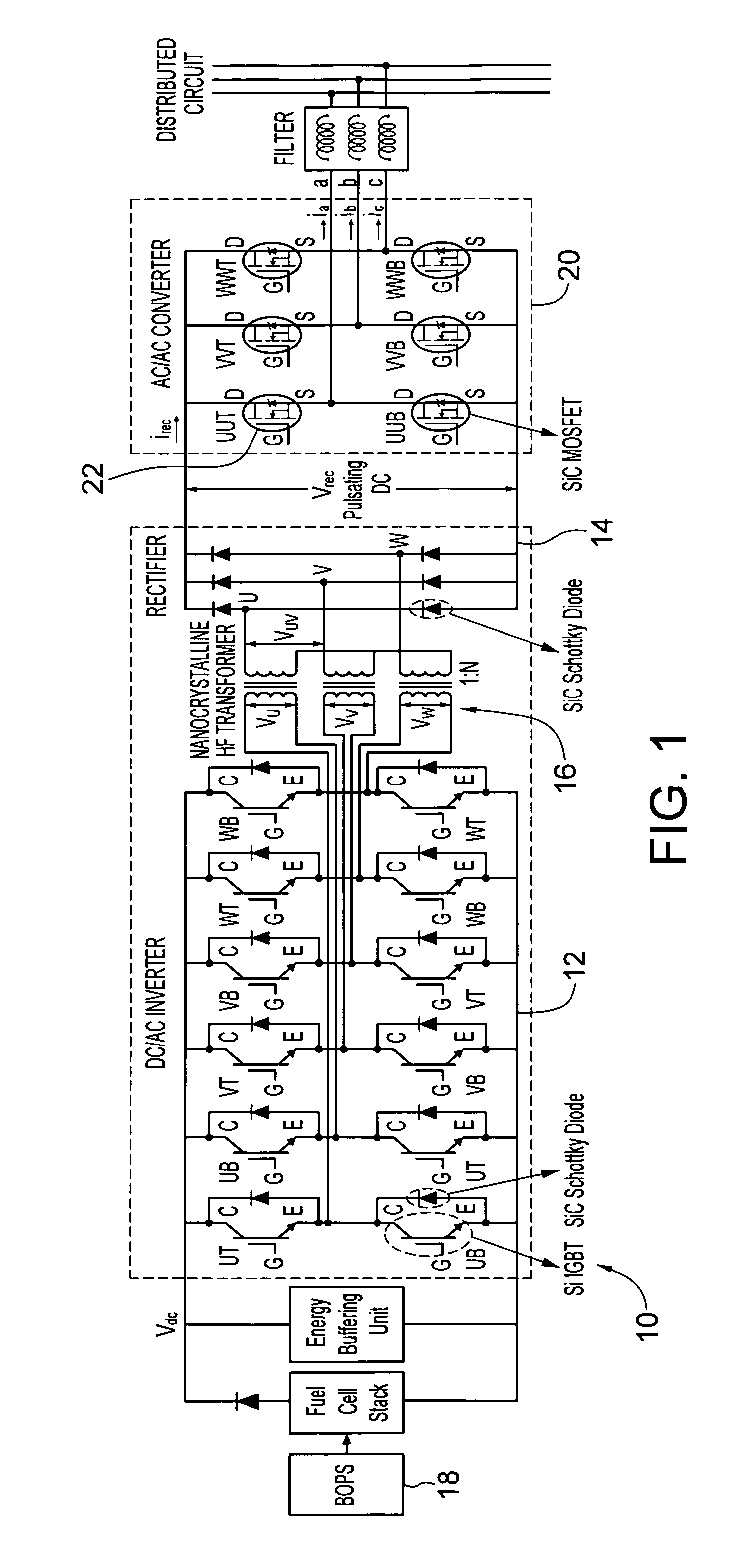
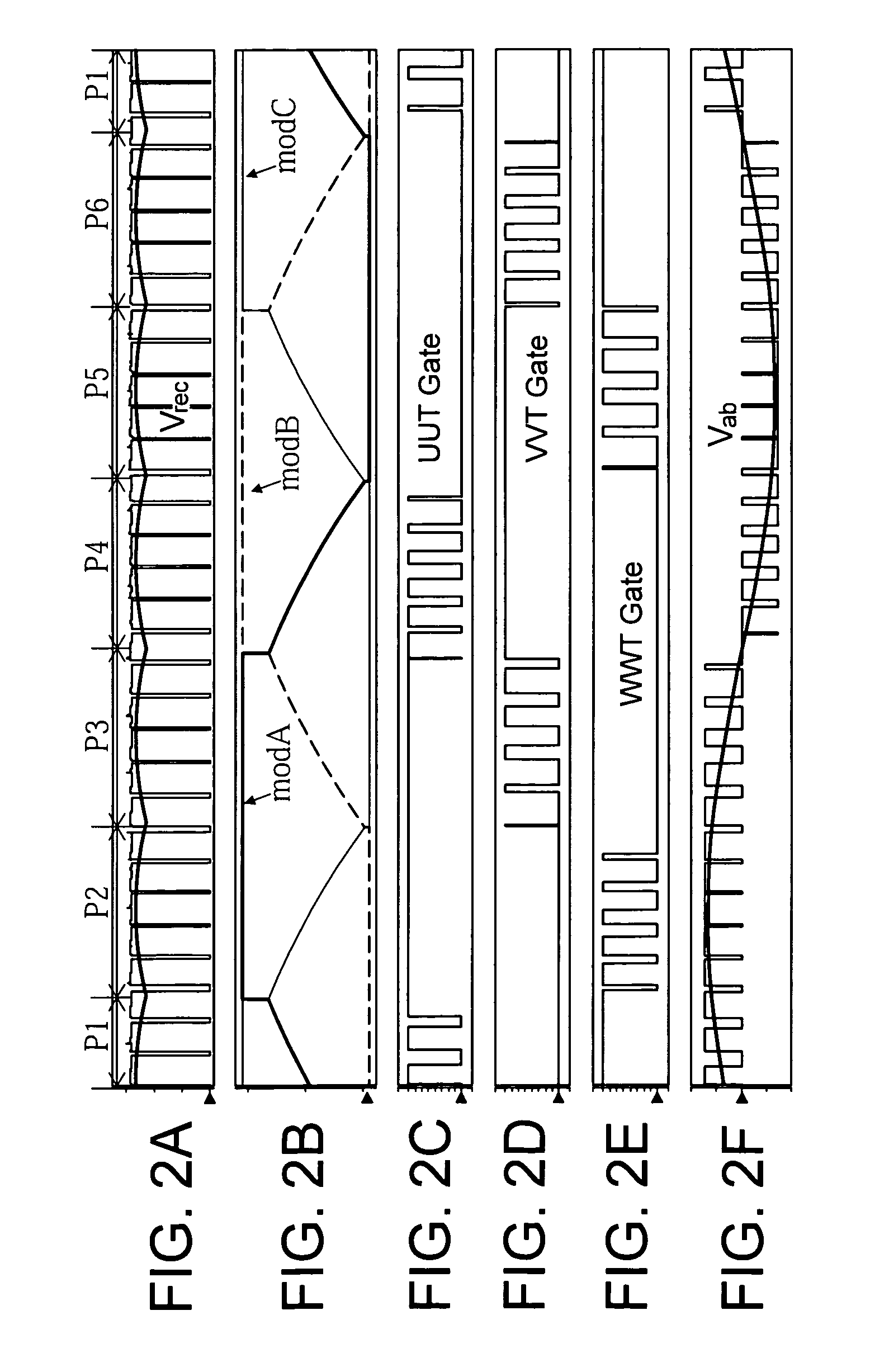
[0111ωt ε[π / 6, π / 3+φ]⊂P2, FIG. 15A: irec switches from −ib to ia when WT turns off, and −ib>ia>0. With their body diodes conduct, switches Q1-Q4 have no effect on operation. The converter has eleven operating modes within each half switching cycle as illustrated in FIG. 15A. The analysis starts at t1 with zero Vrec, irec and itr. Load currents ia, ib, and ic are circulating among three legs of Bridge III before t1.

[0112]Mode 1 (t1-t2): Switch K2 turns off with zero-current at t1; switches WT and WB of Bridge III commutate under ZVS. Both voltage Vpri and Vrec are zeros.

[0113]Mode 2 (t2-t3): K1 turns on at t2. Because of the existence of leakage inductance, the transformer current itr can only rise at a finite rate determined by Vdc / (N·Lk). Therefore, the turn-on loss of K1 is small although it is not strictly a zero-current switching.

[0114]Mode 3 (t3-t4): itr reaches −ib at t3. After that, the transformer leakage inductance resonates with the parasitic capacitance. Vrec increases ra...

case 2 (ωt ′ ε [ π / 2 , π / 3 + φ ] ⊂p3 , fig.15b)

[0131]Case 2 (ωt′ε[π / 2, π / 3+φ]⊂P3, FIG. 15B): In P3, u(t)−w(t) is the modulation references for Bridge I and II, while v(t)−w(t) is used to modulate switches on the leg V. Switches UT and WB remain on in P3. Consequently, irec switches from −ic to ia whenever VT turns off. The eleven operating modes (t′1-t′12) at P3 are similar to the modes (t1-t12) at P2. The soft-switching scheme is also applicable. However, since 0ca, the increasing on irec may cause a narrow dent on Vrec during the interval (t′5-t′6) as shown in FIG. 15B.

case 3 (

[0132ωt ε[π / 3+φ, π / 2]⊂P2): 0ba, the operating modes are similar to Case 2 and the soft-switching of Bridge II summarized in Case 1 is valid as well.


PUM


Abstract

An ac / ac converter for accepting a pulsating dc input with encoded sinusoidal modulation and providing a multiphase modulated output. The converter comprises a bridge including a plurality of switches having switch legs for modulating the pulsating dc input at a carrier frequency over a plurality of phases. The bridge is coupled at one end to a pulsating dc source and coupled at another end to a modulated signal output. A controller is provided for the plurality of switches for causing, for each of the plurality of phases, under unity power factor, one of the switch legs to modulate the pulsating dc input at the carrier frequency while the other switch legs do not modulate the pulsating dc input at the carrier frequency.

Description

PRIORITY CLAIM AND REFERENCE TO RELATED APPLICATIONS[0001]This application claims the benefit of U.S. Provisional Application Ser. Nos. 61 / 013,226, filed Dec. 12, 2007, and 61 / 037,751, filed Mar. 19, 2008, under 35 U.S.C. §119, which are incorporated in their entirety by reference herein.STATEMENT OF GOVERNMENT INTEREST[0002]This invention was made with Government assistance under National Science Foundation Award No. 0725887 and NSF CAREER Award No. 0239131. The Government has certain rights in this invention.FIELD OF THE INVENTION[0003]The invention relates generally to the fields of electrical devices and power systems. The invention relates more particularly to the fields of electrical modulation and conversion.BACKGROUND OF THE INVENTION[0004]Power conversion is often desired for providing particular power sources, for portability of power sources, for providing power in bulk, for transmission, or for other reasons. As one example, a major initiative has been taken recently tow...

Claims


Application Information

Patent Timeline
Patent Type & Authority Patents(United States)
IPC IPC(8): H02M3/335
CPCH02M5/458H02M7/5387H02M2001/007H02M1/0054H02M1/007Y02B70/10
Inventor MAZUMDER, SUDIP K.HUANG, RONGJUN
Owner THE BOARD OF TRUSTEES OF THE UNIV OF ILLINOIS
Learn More