
Protective priming cap for self-sealing male Luer valve

a protective and valve technology, applied in the field of protecting and priming medical connectors, can solve the problems of air embolism with adverse effect on patients, unsatisfactory, harmful to the skin or other tissue of patients,

Active Publication Date: 2010-08-03
CAREFUSION 303 INC
View PDF25 Cites 85 Cited by
  • Summary
  • Abstract
  • Description
  • Claims
  • Application Information

AI Technical Summary

Benefits of technology

The present invention is a system and method for protecting the connection tip of a male connector and providing priming of the connector. The system includes a cap with a reservoir device and an outer housing device. The reservoir device has an internal valve and is attached to the connector. The cap can be easily removed from the connector. The system allows for easy priming of the connector by allowing fluid to flow through the connector and into the reservoir, while venting any gas in the reservoir. The cap can be easily mounted and removed from the connector. The technical effects of the invention include improved protection and priming of medical connectors.

Problems solved by technology

While patients can tolerate receiving a certain level of air from an IV medical fluid line, too high of a level can result in an air embolism with an adverse effect on the patient.
This is not desirable if the fluid that drips out is either expensive or toxic.
Yet a further example is in the oncology area where certain drugs have great beneficial effect when confined to the circulatory system of a patient, yet are harmful to the skin or other tissue of a patient.
Transferring such drugs from one container to another or to the patient's fluid line can be hazardous if seals are not present.
Additionally, Luer fittings are susceptible to being damaged through rough handling and protective caps would not only lower the risk of infection to the patient, but would also lessen the risk of damage to a male Luer connection tip itself.

Method used


Image

  • Protective priming cap for self-sealing male Luer valve
  • Protective priming cap for self-sealing male Luer valve
  • Protective priming cap for self-sealing male Luer valve

Examples


Embodiment Construction

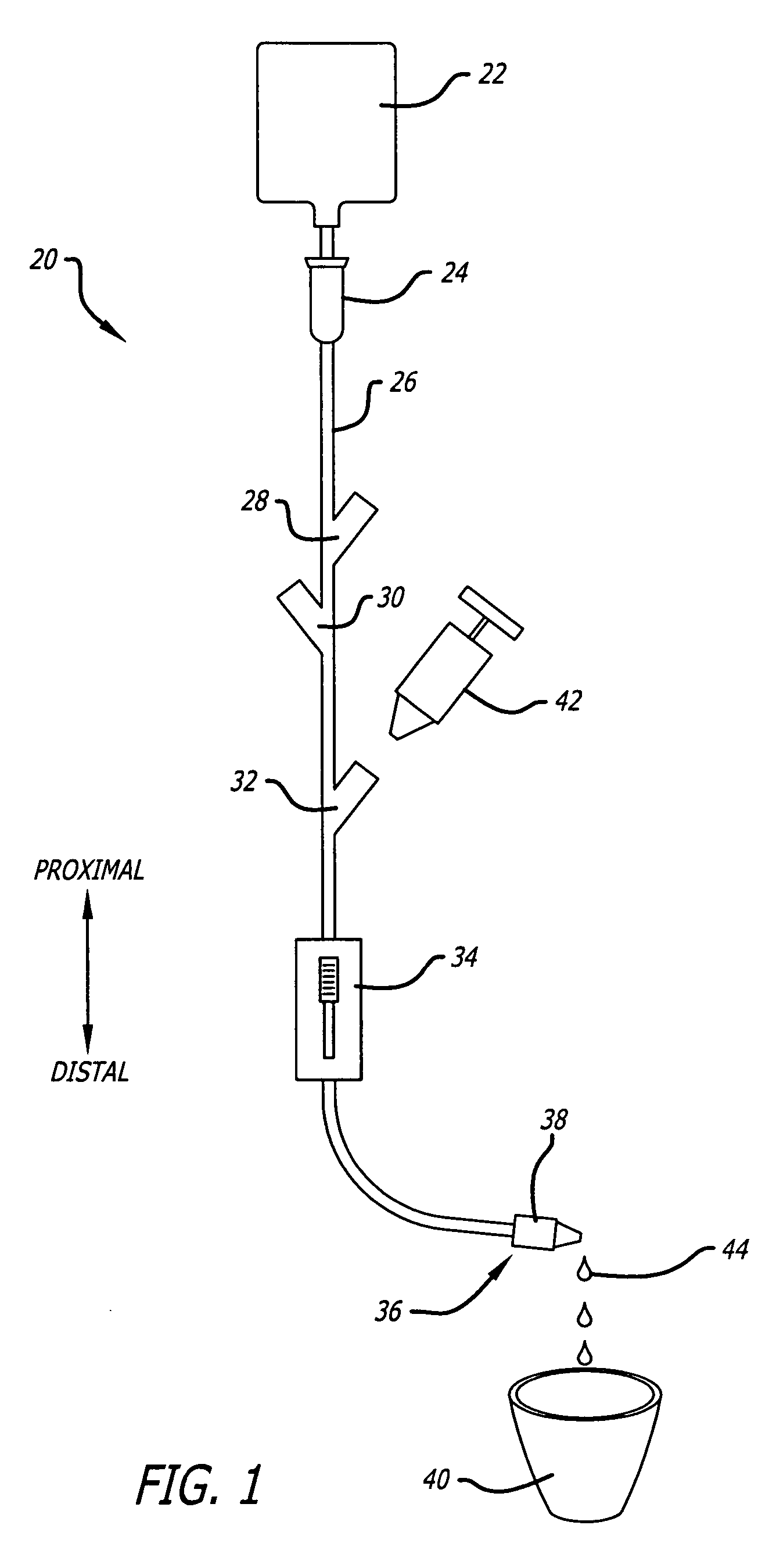
[0026]Referring now to the drawings in more detail in which like reference numerals refer to like or corresponding elements among the views, there is shown in FIG. 1 a view of an IV administration system 20 having a container 22 of medical fluid for administration to a patient, a drip chamber 24, tubing 26, three Y-sites 28, 30, and 32, a roller clamp 34, and a connector 38 located at the distal end 36. A waste-bin 40 is shown for use in priming the IV system. Also shown is a syringe 42 for use in injecting fluid into one of the Y-sites; in this case, the most distal Y-site 32. The syringe may also be used to withdraw fluid from the W set. The FIG. also shows leakage 44 of fluid from the distal end of the IV set into the waste-bin during the priming process.

[0027]As described above in the background section, a clinician would typically hold the distal end connector 38 in one hand and manipulate the roller clamp 34 with the other hand to prime the IV set 20. The clinician watches the...


PUM


Abstract

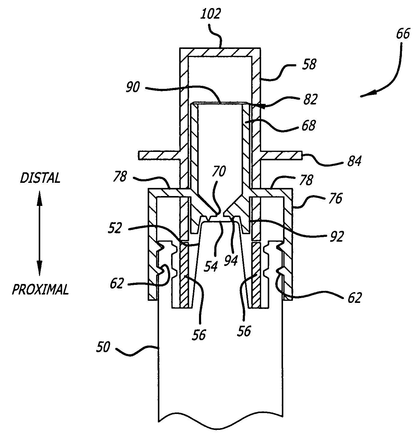
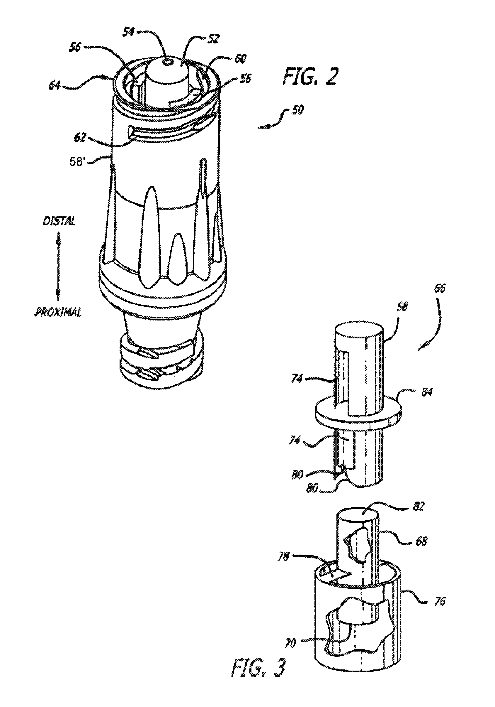
A cap for use in priming a medical connector that has a distal end at which is disposed a distal connection tip with an aperture through which fluid may flow, and the connector having an internal valve. The cap has a reservoir device with an internal volume and a first opening at a proximal end that is connected with the aperture of the connection tip. The reservoir has a second opening at which is disposed an hydrophobic filter for allowing gases to vent to the atmosphere while retaining liquid in the reservoir device. Over the reservoir device is mounted a slidable housing device used to activate the internal valve of the connector to a flow configuration at which fluid flows from the connector into the reservoir device. The user monitors the reservoir device and when gas has been vented so that only liquid remains, the user slides the housing device.

Description

BACKGROUND OF THE INVENTION[0001]The present invention generally relates to a system and method for priming medical administration sets for conducting fluids to patients, and more particularly, to a system and method used for protecting and priming medical connectors.[0002]Many self-sealing connectors presently known and used in the medical art are designed to be connected to a patient's intravenous (“IV”) or gas sampling line, drug or solution source, or other medical device such that the connector's seal operates to trap all fluid on the side of the connector toward the patient in the case of an IV line, on the side of other device such as a fluid bag in the case of a fluid source. Such seals often take the form of a valve located internally to the connector. In the case of many connectors used today, the connection tip has a Luer shape in accordance with ISO 594 whether the connection tip is male or female. In some cases, the Luer connector has an unsealed male Luer connection ti...

Claims


Application Information

Patent Timeline
Patent Type & Authority Patents(United States)
IPC IPC(8): A61M39/10A61M39/00A61M25/16A61M25/18
CPCA61M39/20A61M5/385A61M2205/7536A61M2039/205
Inventor RAMSEY, MICHAEL D.WHITLEY, KENNETH W.PHILLIPS, JOHN C.
Owner CAREFUSION 303 INC
Learn More