Driving system for electronic device and current balancing circuit thereof
a technology of current balancing circuit and electronic device, which is applied in the direction of instruments, light sources, electrical devices, etc., can solve the problems of increasing cost and space, severely requiring illumination and uniform degree, etc., and achieve the effect of not increasing the complexity of the circui
- Summary
- Abstract
- Description
- Claims
- Application Information
AI Technical Summary
Benefits of technology
Problems solved by technology
Method used
Image

Examples
first embodiment
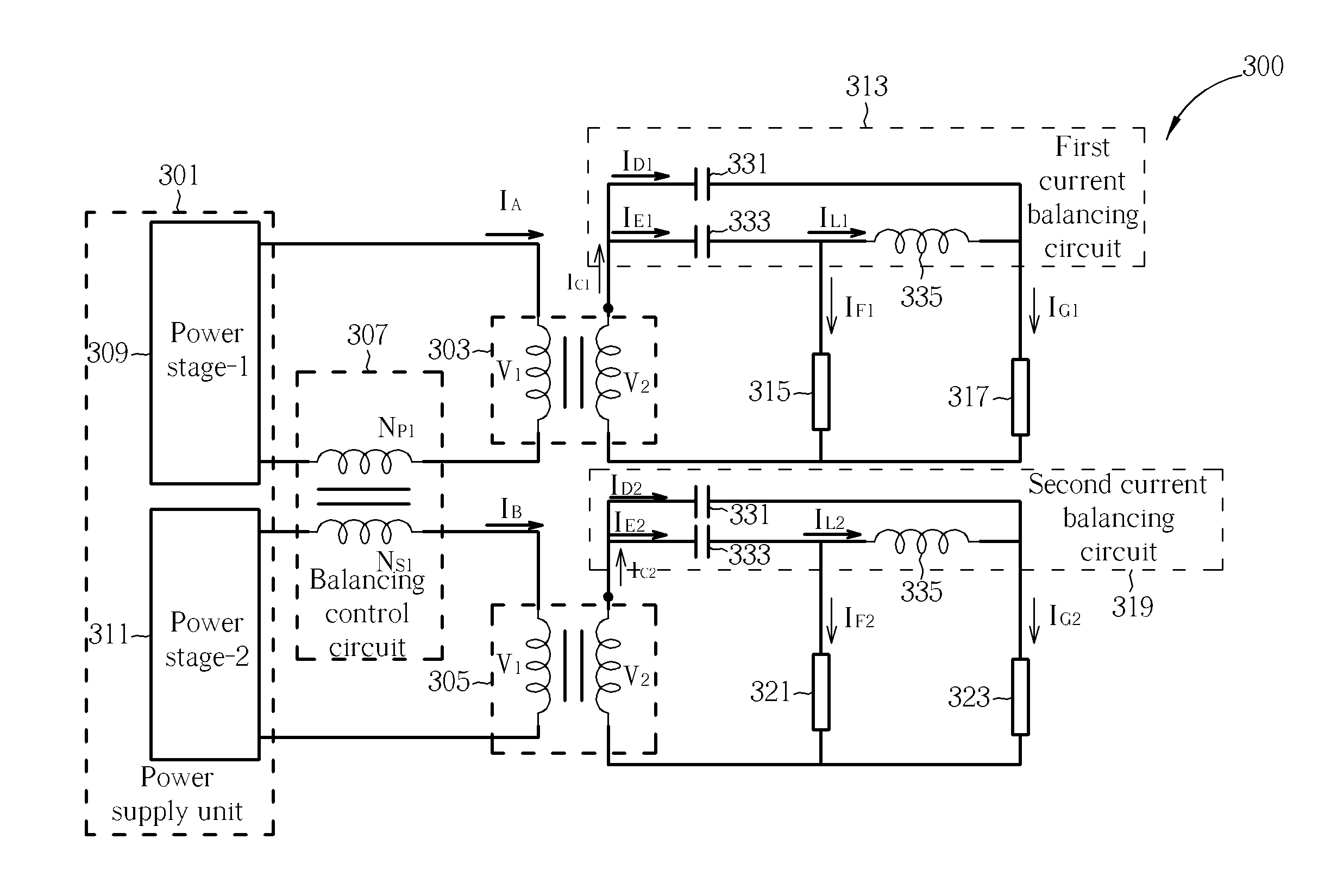
[0018]FIG. 3 is a circuit diagram illustrating a driving system 300 according to the present invention. As shown in FIG. 3, the driving system 300 includes a power supply unit 301, a first transformer 303, a second transformer 305 and a balancing control circuit 307. The power supply unit 301 comprising a first power stage 309 and a second power stage 311 for providing a first current IA and a second current respectively IB. The first transformer 303 has a primary side coupled to the first power stage 309 and a secondary side coupled to a first current balancing circuit 313 for driving a plurality of lamps 315 and 317. The second transformer 305 has a primary side coupled to the second power stage 311 and a secondary side coupled to a second current balancing circuit 319 for driving lamps 321 and 323. The balancing control circuit 307 is coupled to the power supply unit for balancing the first and the second currents IA and IB so that they are substantially equal. It should be noted...
second embodiment
[0027]The structures shown in FIG. 3 can be extended as the structures shown in FIG. 4. FIG. 4 is a circuit diagram illustrating a driving system 400 according to the present invention. The driving system 400 includes: a power supply unit 401, a first transformer 403, a second transformer 405, a third transformer 407, and a balancing control circuit 409. The power supply unit 401 includes a first power stage 411, a second power stage 413 and a third power stage 415 for providing a first current IP1, a second current IP2 and a third current IP3 respectively. The first transformer 403 has a primary side coupled to the first power stage 411 and a secondary side coupled to a first current balancing circuit 417 for driving a plurality of first lamps 419 and 421. The second transformer 405 has a primary side coupled to the second power stage 413 and a secondary side coupled to a second current balancing circuit 423 for driving a plurality of second lamps 425 and 427. The third transformer...
third embodiment
[0038]Also, the balancing control circuit and the power supply unit can have different structures from FIG. 3 and FIG. 4. FIG. 5 is a circuit diagram illustrating a driving system 500 according to the present invention. In this embodiment, the balancing control circuit 501 includes a first impedance 503, a second impedance 505, and a third impedance 507. The first impedance 503 is coupled to the power unit 509 and the primary side of the first transformer 511. The second impedance 505 is coupled to the power unit 509 and the primary side of the second transformer 513. The third impedance 507 is coupled between the primary side of the first transformer 511 and the primary side of the second transformer 513. The first, the second and the third impedance are adapted to balance the first and the second current, so that the first current I1 and the second current I2 are substantially equal.
[0039]In this embodiment, the driving system 500 can further comprise capacitors 515 and 517. Also,...
PUM
 Abstract
Description
Claims
Application Information
 - R&D
- Intellectual Property
- Life Sciences
- Materials
- Tech Scout
- Unparalleled Data Quality
- Higher Quality Content
- 60% Fewer Hallucinations
Browse by: Latest US Patents, China's latest patents, Technical Efficacy Thesaurus, Application Domain, Technology Topic, Popular Technical Reports.
© 2025 PatSnap. All rights reserved.Legal|Privacy policy|Modern Slavery Act Transparency Statement|Sitemap|About US| Contact US: help@patsnap.com